
R2511-HP MSR Router Series MPLS Configuration Guide(V5)

381
[RouterA-Tunnel1] destination 2.2.2.2
[RouterA-Tunnel1] mpls te tunnel-id 10
[RouterA-Tunnel1] mpls te signal-protocol rsvp-te
[RouterA-Tunnel1] mpls te commit
[RouterA-Tunnel1] return
Verifying the configuration
# Display detailed information about the BFD session between Router A and Router B.
<RouterA> display bfd session verbose
Total Session Num: 1 Init Mode: Active
Session Working Under Ctrl Mode:
Local Discr: 19 Remote Discr: 18
Source IP: 12.12.12.1 Destination IP: 12.12.12.2
Session State: Up Interface: Ethernet1/1
Min Trans Inter: 400ms Act Trans Inter: 400ms
Min Recv Inter: 400ms Act Detect Inter: 2000ms
Running Up for: 00:00:01 Auth mode: None
Connect Type: Direct Board Num: 6
Protocol: RSVP
Diag Info: No Diagnostic
Configuring MPLS TE using CR-LDP
Network requirements
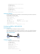
Router A, Router B, Router C and Router D are running OSPF and all of them are in area 0.
Use CR-LDP to create a TE tunnel from Router A to Router D, making sure that the maximum bandwidth
of each link that the tunnel traverses is 10000 kbps and the maximum reservable bandwidth is 5000
kbps.
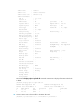
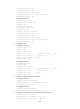
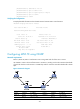
Figure 97 Network diagram
Device Interface IP address Device Interface IP address
Router A Loop0 1.1.1.9/32
Router D
Loop0
4.4.4.9/32
Eth 1/1 10.1.1.1/24
Eth 1/1
30.1.1.2/24
Router B Loop0 2.2.2.9/32 Router C Loop0 3.3.3.9/32