
R2511-HP MSR Router Series MPLS Configuration Guide(V5)

389
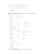
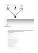
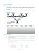
Figure 98 Network diagram
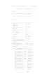
Device Interface IP address
Device
Interface
IP address
Router A Loop0 1.1.1.9/32 Router D Loop0 4.4.4.9/32
Eth 1/1 10.1.1.1/24
POS 5/0
30.1.1.2/24
POS 5/1 30.1.1.1/24
POS 5/1
40.1.1.1/24
Router B Loop0 2.2.2.9/32 Router C Loop0 3.3.3.9/32
Eth 1/1 10.1.1.2/24
Eth 1/1
20.1.1.2/24
Eth 1/2 20.1.1.1/24
POS 5/1
40.1.1.2/24
Configuration procedure
1. Configure IP addresses and masks for the interfaces according to Figure 98. (Details not shown.)
2. Enable IS-IS to advertise host routes with LSR IDs as destinations on each node. (Details not shown.)
# Verify that all nodes have learned the host routes of other nodes with LSR IDs as destinations.
3. Configure basic MPLS TE, and enable RSVP-TE and CSPF:
# Configure Router A.
<RouterA> system-view
[RouterA] mpls lsr-id 1.1.1.9
[RouterA] mpls
[RouterA-mpls] mpls te
[RouterA-mpls] mpls rsvp-te
[RouterA-mpls] mpls te cspf
[RouterA-mpls] quit
[RouterA] interface ethernet 1/1
[RouterA-Ethernet1/1] mpls
[RouterA-Ethernet1/1] mpls te
[RouterA-Ethernet1/1] mpls rsvp-te
[RouterA-Ethernet1/1] quit
[RouterA] interface pos 5/1
[RouterA-POS5/1] mpls
[RouterA-POS5/1] mpls te
[RouterA-POS5/1] mpls rsvp-te
[RouterA-POS5/1] quit
Router A
Loop0
Eth1/1
Router B
Router C
Router D
Loop0
Loop0
Eth1/1
Eth1/2
Eth1/1
POS5/1 POS5/1
POS5/0
POS5/1
Loop0