
R2511-HP MSR Router Series MPLS Configuration Guide(V5)

392
Configuring FRR
Network requirements
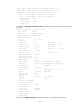
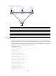
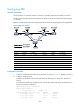
On the LSP Router A Router B Router C Router D, use FRR to protect the link Router B Router C.→→ → →
Create a bypass LSP that traverses the path Router B Router E Router C. Router B is the PLR and Router →→
C is the MP.
Explicitly route the primary TE tunnel and the bypass TE tunnel with the signaling protocol being RSVP-TE.
Figure 99 Network diagram
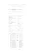
Device Interface IP address
Device
Interface
IP address
Router A Loop0 1.1.1.1/32
Router E
Loop0
5.5.5.5/32
Eth 1/1 2.1.1.1/24 POS 5/0 3.2.1.2/24
Router B Loop0 2.2.2.2/32
POS 5/1
3.3.1.1/24
Eth 1/1 2.1.1.2/24
Router C
Loop0
3.3.3.3/32
Eth 1/2 3.1.1.1/24 Eth 1/1 4.1.1.1/24
POS 5/0 3.2.1.1/24
Eth 1/2
3.1.1.2/24
Router D Loop0 4.4.4.4/32
POS 5/0
3.3.1.2/24
Eth 1/1 4.1.1.2/24
Configuration procedure
1. Configure IP addresses and masks for the interfaces according to Figure 99. (Details not shown.)
2. Configure the IGP protocol:
# Enable IS-IS to advertise host routes with LSR IDs as destinations on each node. (Details not
shown.)
# Verify that all nodes have learned the host routes of other nodes with LSR IDs as destinations on
Routers, for example, on Router A.
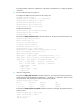
<RouterA> display ip routing-table
Routing Tables: Public
Destinations : 13 Routes : 13
Destination/Mask Proto Pre Cost NextHop Interface
1.1.1.1/32 Direct 0 0 127.0.0.1 InLoop0
2.1.1.0/24 Direct 0 0 2.1.1.1 Eth1/1
2.1.1.1/32 Direct 0 0 127.0.0.1 InLoop0