
R2511-HP MSR Router Series MPLS Configuration Guide(V5)

401
# Execute the display ip routing-table command on Router A. The output shows a static route entry
with Tunnel4 as the outgoing interface.
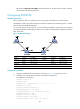
Configuring IETF DS-TE
Network requirements
Router A, Router B, Router C, and Router D are running IS-IS and all of them are Level-2 routers.
Use RSVP-TE to create a TE tunnel from Router A to Router D. Traffic of the tunnel belongs to CT 2, and the
tunnel needs a bandwidth of 4000 kbps.
For each link that the tunnel traverses, set the maximum bandwidth to 10000 kbps, the maximum
reservable bandwidth to 10000 kbps, and BC 1, BC 2, and BC 3 to 8000 kbps, 5000 kbps, and 2000
kbps, respectively.
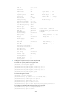
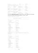
Figure 100 Network diagram
Device Interface IP address
Device
Interface
IP address
Router A Loop0 1.1.1.9/32 Router C Loop0 3.3.3.9/32
Eth1/1 10.1.1.1/24
Eth1/1
30.1.1.1/24
Router B Loop0 2.2.2.9/32
POS5/0
20.1.1.2/24
Eth1/1 10.1.1.2/24 Router D Loop0 4.4.4.9/32
POS5/0 20.1.1.1/24
Eth1/1
30.1.1.2/24
Configuration procedure
1. Configure IP addresses for the interfaces according to Figure 100. (Details not shown.)
2. Configure IS-IS, and advertise host routes with LSR IDs as destinations:
# Configurations on Router A.
<RouterA> system-view
[RouterA] isis 1
[RouterA-isis-1] network-entity 00.0005.0000.0000.0001.00
[RouterA-isis-1] quit
[RouterA] interface ethernet 1/1
[RouterA-Ethernet1/1] isis enable 1
[RouterA-Ethernet1/1] isis circuit-level level-2
[RouterA-Ethernet1/1] quit
[RouterA] interface loopback 0
[RouterA-LoopBack0] isis enable 1
[RouterA-LoopBack0] isis circuit-level level-2