
R2511-HP MSR Router Series MPLS Configuration Guide(V5)

424
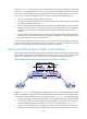
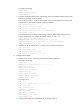
As shown in Figure 103, the access network is an MPLS L2VPN. PE 1 and PE 2 are PE devices of the MPLS
L2VPN. PE 1 is connected to VPN site 1. PE 2 is connected to the MPLS L3VPN/IP backbone through PE
3. PE 3 acts as a PE on the MPLS L3VPN/IP backbone and as a CE on the MPLS L2VPN at the same time.
A user in VPN 1 accesses the MPLS L3VPN or IP backbone through MPLS L2VPN in this way:
• The user is connected to the MPLS L2VPN through PE 1.
• PE 1 establishes an MPLS L2VPN tunnel with PE 2, and transparently transfers Layer 2 packets of the
user through the MPLS L2VPN tunnel.
• PE 2, the endpoint of the MPLS L2VPN tunnel, terminates MPLS L2VPN packets. It removes the MPLS
label from a packet to obtain the original Layer 2 packet, and sends the packet to the connected CE,
namely PE 3. The interface terminating MPLS L2VPN packets is referred to as the "terminating
interface."
• PE 3 receives the Layer 2 packet from PE 2, looks up the routing table, and forwards the packet to
the destination through the MPLS L3VPN or IP backbone. The interface receiving the Layer 2 packet
from PE 2 is referred to as the "access interface."
In the conventional networking mode, two devices (PE 2 and PE 3 in this example) are required to
connect the MPLS L2VPN with the MPLS L3VPN or IP backbone: one (PE 2) for terminating the MPLS
L2VPN, and the other (PE 3) for accessing the MPLS L3VPN or IP backbone.
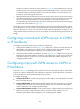
Improved L2VPN access to L3VPN or IP backbone
In the improved networking mode, the functions of the two devices that connect the MPLS L2VPN and the
MPLS L3VPN or IP backbone can be implemented on one device. Thus, you can reduce the number of
devices to be deployed, lowering the networking cost and the network deployment complexity.
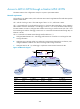
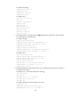
Figure 104 Network diagram for improved L2VPN access to L3VPN or IP backbone
As shown in Figure 104, the PE Aggregation (PE-agg) device connects the MPLS L2VPN with the MPLS
L3VPN or IP backbone. PE-agg terminates the MPLS L2VPN and also provides access to the MPLS L3VPN
or IP backbone, implementing the functions of both PE 2 and PE 3 in Figure 103. T
o configure the PE-agg:
• Create a terminating virtual Ethernet (VE) interface on the PE-agg to terminate MPLS L2VPN packets.
This interface is referred to as the VE-L2VPN-Terminate interface. The functions and configurations
of the terminating VE interface are similar to those of the terminating interface in Figure 103.
• Cr
eate an access VE interface on the PE-agg to provide access to the backbone. This interface is
referred to as the VE-L3VPN-Access interface. The functions and configurations of the access VE