
R2511-HP MSR Router Series MPLS Configuration Guide(V5)
425
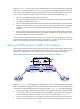
interface are similar to those of the access interface in Figure 103. The IP address of the access VE
interface must be in the same network segment as the CE-PE interface of CE 1. When the backbone
is an MPLS L3VPN, bind the VPN instance to the access VE interface, so that the interface can
forward user packets through the VPN routes.
• Add the terminating VE interface and the access VE interface to the same VE group. The terminating
VE interface directly delivers the obtained Layer 2 packets to the access VE interface in the same VE
group. The terminating VE interface and access VE interface in the same VE group can be
considered directly connected through a physical link, like the physical link between the terminating
interface and access interface in Figure 103.
T
he PE-agg connects the MPLS L2VPN and the backbone through the terminating VE interface and the
access VE interface. You can assume that the MPLS L2VPN is connected to the backbone through an
Ethernet or VLAN link. If a user is not connected to the MPLS L2VPN through Ethernet or VLAN, you must
configure MPLS L2VPN interworking on the user access PE (PE 1) and the terminating VE interface of the
PE-agg.
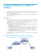
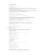
Configuring conventional L2VPN access to L3VPN
or IP backbone
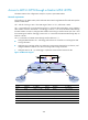
To configure conventional L2VPN access to L3VPN or IP backbone:
• Configure MPLS L2VPN. As shown in Figure 103,
configure PE 1 and PE 2 as the PE devices of the
MPLS L2VPN, and configure CE 1 and PE 3 as the CE devices of the MPLS L2VPN. For more
information about MPLS L2VPN configuration, see "Configuring MPLS L2VPN."
• Configure the MPLS L3VPN or IP backbone. As shown in Figure 103,
configure PE 3 and PE 4 as
the PE devices of the MPLS L3VPN or IP network, and configure CE 1 and CE 2 as the CE devices
of the MPLS L3VPN or IP network. For more information about MPLS L3VPN configuration, see
"Configuring MPLS L3VPN."
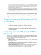
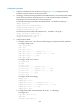
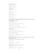
Configuring improved L2VPN access to L3VPN or
IP backbone
As shown in Figure 104, the PE-agg must provide the functions of two PEs (PE 2 and PE 3), and therefore
requires some special configurations. The configurations required on all the other devices are similar to
those on the devices in the conventional L2VPN access scenario.
To configure the PE-agg:
• Configure VE interfaces—Create a terminating VE interface and an access VE interface, and add
them to the same VE group.
• Configure MPLS L2VPN—Enable L2VPN and MPLS L2VPN, create the remote LDP peer, and create
an MPLS L2VPN connection on the terminating VE interface. For more information about MPLS
L2VPN configuration, see "Configuring MPLS L2VPN."
• Configure MPLS L3VPN or IP routes—Create a VPN instance, configure PE-CE route exchange and
PE-PE route exchange, and bind the VPN instance with the access VE interface. For more
information about MPLS L3VPN configuration, see "Configuring MPLS L3VPN."