
R2511-HP MSR Router Series MPLS Configuration Guide(V5)

428
Access to MPLS L3VPN through a Martini MPLS L2VPN
The MPLS L2VPN in this configuration example is a point-to-point MPLS L2VPN.
Network requirements
The backbone is an MPLS L3VPN, which advertises VPN routes through BGP and forwards VPN packets
based on MPLS labels.
CE 1 and CE 2 belong to VPN 1. The VPN target of VPN 1 is 111:1, and the RD is 200:1.
CE 1 is connected to PE 1 through interface Serial 2/0, which uses PPP encapsulation. Set up a Martini
MPLS L2VPN connection between PE 1 and PE-agg, so that CE 1 can access the MPLS L3VPN through
the MPLS L2VPN connection. Configure MPLS L2VPN interworking on interface Serial 2/0 of PE 1 and
the terminating VE interface of PE-agg, because CE 1 is connected to the MPLS L2VPN through PPP, not
Ethernet or VLAN.
CE 2 is connected to the MPLS L3VPN through interface Ethernet 1/1.
• Configure EBGP between CE 1 and PE-agg and between CE 2 and PE 2 to exchange the VPN
routing information.
• Configure IS-IS on PE-agg and PE 2 to implement communication between the two devices, and
configure MP-IBGP so that the two devices exchange VPN routing information.
• Configure OSPF on PE 1, P, and PE-agg to implement communication between the PEs.
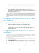
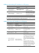
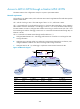
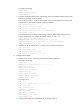
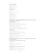
Figure 105 Network diagram
Device Interface IP address
Device
Interface
IP address
CE 1 S2/0 100.1.1.1/24 PE-agg Loop0 3.3.3.9/32
PE 1 Loop0 1.1.1.9/32
POS5/0
10.2.2.2/24
POS5/0 10.2.1.1/24
POS5/1
10.3.3.1/24
P Loop0 2.2.2.9/32 VE-L3VPN-Access1 100.1.1.2/24
POS5/0 10.2.1.2/24
PE 2
Loop0
4.4.4.9/32
POS5/1 10.2.2.1/24
POS5/0
10.3.3.2/24
CE 2 Eth1/1 100.2.1.2/24 Eth1/1 100.2.1.1/24
CE 2
MPLS L3VPN
backbone
PE 2
MPLS L2VPN
access network
PE 1
CE 1
Loop0
PE-aggP
Loop0
Loop0
Loop0
S2/0
POS5/0
POS5/0
POS5/1
POS5/0
POS5/1
POS5/0
Eth1/1
Eth1/1
VPN 1
AS 65010
VPN 1
AS 65020
S2/0
POS5/0
POS5/1
VE-L2VPN-
Terminate 1
VE-L3VPN-
Access 1