
R2511-HP MSR Router Series MPLS Configuration Guide(V5)


37
MPLS L2VPN network models
MPLS L2VPN network models include remote connection model and local connection model.
Remote connection model
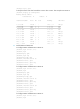
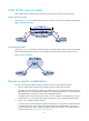
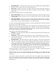
As shown in Figure 15, this model connects two Layer 2 customer networks over an MPLS or IP backbone.
Figure 15 Remote connection
Local connection model
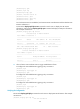
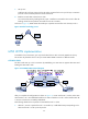
As shown in Figure 16, this model connects two Layer 2 customer networks to the same PE. The customer
networks exchange packets with each other through the PE. The PE functions like a Layer 2 switch.
Figure 16 Local connection
Remote connection establishment
To set up a remote MPLS L2VPN connection between two CEs over a backbone network:
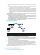
1. Set up a public tunnel to forward user packets from the local PE to the remote PE.
The public tunnel can be an LSP, MPLS TE, or GRE tunnel. For more information about LSP and
MPLS TE tunnels, see "Configuring basic MPLS" and "Configuring MPLS TE." For more information
about GRE tunnels, see Layer 3—IP Services Configuration Guide.
If multiple public tunnels exist between two PEs, you can configure a tunneling policy to control
tunnel selection. For more information about tunneling policy, see "Configuring MPLS L3VPN."
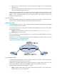
2. Set up a VC to identify customer networks.
To set up a VC, the two PEs assign VC labels to each other to set up a pair of unidirectional LSPs
in opposite directions. By VC setup mode, MPLS L2VPN can be implemented in Circuit Cross
Connect (CCC) mode, Static Virtual Circuit (SVC) mode, Martini mode, or Kompella mode. For
more information, see "MPLS L2VPN implementation."