
R2511-HP MSR Router Series MPLS Configuration Guide(V5)


42
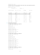
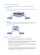
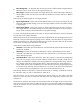
Figure 21 VC label calculation
As shown in Figure 21, PEs calculates VC labels for a VC as follows (take the VC between CE 1 and CE
12 as an example):
• PE 1 calculates the VC label it assigns to the VC:
PE 1 compares the ID (12) of the peer CE (CE 12) with the label blocks assigned by PE 1. If a label
block meets LO<=CE ID<LO+LR, PE 1 assigns a label from the label block. In this example, label
block 2 (1055/5/10) meets LO<=CE ID<LO+LR (5<=12<5+10). PE 1 assigns a label to the VC
from label block 2. The assigned label value = LB+CE ID-LO, namely 1062 (1055+12-5).
• PE 1 calculates the VC label that PE 2 assigns to the VC:
PE 1 compares the ID (1) of the local CE (CE 1) with the label blocks assigned by PE 2. A label
block that meets LO<=CE ID<LO+LR is used by PE 2 to assign a label value to the VC. In this
example, label block (3000/0/15) meets LO<=CE ID<LO+LR (0<=1<0+15). PE 2 assigns a label
value to the VC from the label block. The assigned label value = LB+CE ID-LO, namely 3001
(3000+1-0).
• PE 2 performs the same calculations and gets the same results: the VC label that PE 2 assigns to the
VC is 3001 and that PE 1 assigns to the VC is 1062.
A PE adds the VC label assigned by the peer PE into a Layer 2 packet from a local CE. For example,
when PE 1 forwards packets from CE 1 to CE 2, it adds VC label 3001.
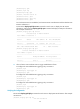
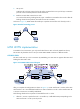
Figure 22 Label distribution in Kompella mode
VPN 1
CE 1
CE 2
PE 1 PE 2
P
VPN 1 VPN 1
Label block 1: 1000/0/5
Label block 2: 1055/5/10
CE 12
Label block for CE 2: 2000/0/15
Label block for CE 12: 3000/0/15
VC connected CE 1 and CE 2:
local VC label: 1002
remote VC label: 2001
VC connected CE 1 and CE 12:
local VC label: 1062
remote VC label: 3001
VC connected CE 1 and CE 2:
local VC label: 2001
remote VC label: 1002
VC connected CE 1 and CE 12:
local VC label: 3001
remote VC label: 1062
Label block allocated Label block allocated
VC labels calculated