
R2511-HP MSR Router Series MPLS Configuration Guide(V5)

46
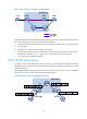
For more information about ATM, see Layer 2—WAN Configuration Guide.
Figure 23 ATM AAL5 transparent transport
Control word
The control word field is between the VC label and the Layer 2 data. It carries information about the Layer
2 packet, such as the sequence number.
The control word filed has the following functions:
• Avoid packet disorder—In case of multi-path forwarding, packets received might be disordered.
You can configure the control word function on the device, so the device can reorder the packets
according to the sequence number carried in the control word field.
• Transfer specific Layer 2 frame tags—When a PE processes Layer 2 packets, it might discard some
information, such as the FECN bit and BECN bit of Frame Relay. A PE can copy such information
to the control word field before sending Layer 2 packets to the peer PE, so the peer PE can correctly
process the Layer 2 packets.
• Add payload length—If the payload of a packet to be transmitted on a VC is less than 64 bytes, you
can add the control word field to the packet to increase the packet payload length to avoid
transmission failure.
For some VC encapsulation types, such as FR DLCI and ATM AAL5 transparent transport, packets
transmitted on a VC always carry the control word field. For some VC encapsulation types, such as PPP,
HDLC, and FR port mode, the control word field is optional, and you can configure whether to carry the
control field in packets. If you enable the control word function on both PEs of a VC, packets transmit on
the VC carry the control word field. Otherwise, packets do not carry the control word field.
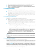
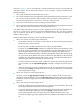
VC redundancy
Only SVC and Martini VCs support VC redundancy.
If only one VC exists between two CEs, when this VC fails, the two CEs cannot communicate. With VC
redundancy, as shown in Figure 24, t
wo VCs (one primary and one backup) are established between CE
1 and CE 2. The CEs communicate through the primary VC. When the primary VC goes down, they
continue to communicate through the backup VC. More specifically, when PE 1 detects the failure of the
primary VC, it brings up the backup VC and then forwards packets from CE 1 to CE 2 through the
backup VC. When CE 2 receives the packet, it updates its MAC address table, so that packets from CE
2 travel through the backup VC, too.