
R2511-HP MSR Router Series MPLS Configuration Guide(V5)
48
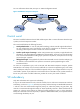
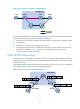
As shown in Figure 25, CE 1 is connected to PE 1 through an Ethernet link and CE 2 is connected to PE
2 through a PPP link. The VC setup mode is Martini. In such a scenario, a packet is forwarded in the
following procedure:
1. CE 1 sends an Ethernet frame destined for CE 2 to PE 1.
2. PE 1 checks whether the packet encapsulated in the received Ethernet frame is an IP packet. If yes,
PE 1 removes the Ethernet header, adds VC label V and tunnel label T to the IP packet, and
forwards the resulting packet to the P device. If not, PE 1 drops the frame.
3. Device P forwards the packet to PE 2 according to the tunnel label T.
4. PE 2 removes the tunnel label and the VC label, adds a PPP header (the link type between PE 2 and
CE 2 is PPP) to the packet, and sends the resulting PPP frame to CE 2.
In an MPLS L2VPN interworking scenario, link layer negotiation packets cannot be delivered on the
network. As a result, Layer 2 connections cannot be established between CEs. CEs need to establish
Layer 2 connections with the PEs. For example, CE 2 and PE 2 need to perform PPP negotiation to
establish a PPP connection.
To deploy MPLS L2VPN interworking, observe the following restrictions:
• When a CE connects to a PE through an Ethernet link:
{ On the Ethernet network or in the VLAN, Layer 2 devices are allowed, but the CE and PE must
be the only Layer 3 network devices.
{ The PE responds to all ARP requests from the CE with its own MAC address.
{ On the PE, use the default-nexthop command to configure the default next hop address, so that
the PE can correctly encapsulate a link layer header for the packets destined for the CE. If you
specify the MAC address of the CE or a broadcast MAC address as the default next hop
address, the PE uses the MAC address as the destination address of the packets to be sent to the
CE. If you specify the IP address of the CE as the default next hop address, the PE resolves the
IP address to a MAC address through ARP and then uses the obtained MAC address as the
destination MAC address of the packets to be sent to the CE.
{ On the CE's interface connected to the PE, configure the network type of the routing protocol as
P2P. For example, use the ospf network-type p2p command to configure the network type as
P2P.
{ When you remove the interworking configuration on the PE, clear the ARP entries on the CE as
well by using the reset arp command. Thus, the CE can learn new ARP entries, preventing traffic
from being dropped wrongly.
• When a CE connects to a PE through a PPP link:
On the PE, execute the ppp ipcp ignore local-ip command to configure the PE to support IPCP
negotiation without IP address, or execute the ppp ipcp proxy command to specify the IP address
for the PE to use for IPCP negotiation with the CE. Choose the address negotiation mode supported
by the CE.
• When a CE connects to a PE through a FR link:
{ On the PE, configure the interworking feature on an FR point-to-point sub-interface. Only an FR
point-to-point sub-interface supports the interworking feature.
{ On the CE, configure the interface connected to the PE as an FR point-to-point sub-interface or
configure a static address mapping by using the fr map ip command because an FR
point-to-point subinterface does not support the Inverse Address Resolution Protocol. HP
recommends configuring the static mapping's destination address as the address of the remote
CE.