
R2511-HP MSR Router Series MPLS Configuration Guide(V5)


64
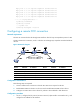
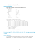
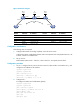
Figure 27 Network diagram
Configuration considerations
Because a local CCC connection is bidirectional, one local CCC connection is enough for CE 1 and CE
2 to communicate with each other.
Because the PE-CE 1 link type is FR, and the PE-CE 2 link type is ATM, you must configure the local CCC
connection on the PE to support IP interworking.
Configuration procedure
1. Configure CE 1:
# Configure the link protocol as frame relay on Serial 2/0, the interface connected to the PE.
<Sysname> system-view
[Sysname] sysname CE1
[CE1] interface serial 2/0
[CE1-Serial2/0] link-protocol fr
[CE1-Serial2/0] quit
# Create point-to-point subinterface Serial 2/0.1, and assign a frame relay virtual circuit and an
IP address to it.
[CE1] interface serial 2/0.1 p2p
[CE1-Serial2/0.1] fr dlci 100
[CE1-fr-dlci-Serial2/0.1-100] quit
[CE1-Serial2/0.1] ip address 100.1.1.1 24
[CE1-Serial2/0.1] quit
2. Configure the PE:
# Configure the LSR ID and enable MPLS globally.
<Sysname> system-view
[Sysname] sysname PE
[PE] interface loopback 0
[PE-LoopBack0] ip address 172.1.1.1 32
[PE-LoopBack0] quit
[PE] mpls lsr-id 172.1.1.1
[PE] mpls
[PE-mpls] quit