
R2511-HP MSR Router Series MPLS Configuration Guide(V5)


70
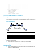
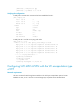
Figure 29 Network diagram
Device Interface IP address
Device
Interface
IP address
CE 1 POS5/0 100.1.1.1/24
CE 2
POS5/0
100.1.1.2/24
PE 1 Loop0 192.2.2.2/32 P Loop0 192.4.4.4/32
POS5/1 10.1.1.1/24
POS5/0
10.2.2.2/24
PE 2 Loop0 192.3.3.3/32
POS5/1
10.1.1.2/24
POS5/0 10.2.2.1/24
Configuration considerations
The following steps are required:
1. Configure MPLS basic forwarding capability on the PEs and P router:
Configure the LSR ID, enable MPLS and LDP, and run IGP (OSPF in this example) between PE 1, the
P device, and PE 2 to establish LSPs.
2. Set up an SVC:
Enable MPLS L2VPN on PE 1 and PE 2, create a static VC, and specify the VC labels.
Configuration procedure
1. On CE 1, configure the link protocol as PPP on POS 5/0 (the interface connected to PE 1), and
configure an IP address for the interface.
<Sysname> system-view
[Sysname] sysname CE1
[CE1] interface pos 5/0
[CE1-POS5/0] link-protocol ppp
[CE1-POS5/0] ip address 100.1.1.1 24
2. Configure PE 1:
# Configure the LSR ID and enable MPLS globally.
<Sysname> system-view
[Sysname] sysname PE1
[PE1] interface loopback 0
[PE1-LoopBack0] ip address 192.2.2.2 32
[PE1-LoopBack0] quit
[PE1] mpls lsr-id 192.2.2.2
[PE1] mpls
[PE1-mpls] quit
CE 1
CE 2
SVC
PE 1 PE 2P
POS5/1
POS5/1
POS5/0
POS5/0
POS5/0
POS5/1
POS5/0
POS5/0
Loop0 Loop0 Loop0