
R2511-HP MSR Router Series MPLS Configuration Guide(V5)


74
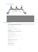
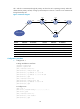
Figure 30 Network diagram
Device Interface IP address
Device
Interface
IP address
CE 1 S2/0 100.1.1.1/24
CE 2
S2/0
100.1.1.2/24
PE 1 Loop0 192.2.2.2/32 P Loop0 192.4.4.4/32
S2/1 10.1.1.1/24
S2/0
10.1.1.2/24
PE 2 Loop0 192.3.3.3/32
S2/1
10.2.2.2/24
S2/1 10.2.2.1/24
Configuration procedure
1. On CE 1, configure the link protocol type as PPP on Serial 2/0 (the interface connected to the PE
1), and configure an IP address for the interface.
<Sysname> system-view
[Sysname] sysname CE1
[CE1] interface serial 2/0
[CE1-Serial2/0] link-protocol ppp
[CE1-Serial2/0] ip address 100.1.1.1 24
2. Configure PE 1:
# Configure the LSR ID and enable MPLS globally.
<Sysname> system-view
[Sysname] sysname PE1
[PE1] interface loopback 0
[PE1-LoopBack0] ip address 192.2.2.2 32
[PE1-LoopBack0] quit
[PE1] mpls lsr-id 192.2.2.2
[PE1] mpls
[PE1-mpls] quit
# Enable L2VPN and MPLS L2VPN.
[PE1] l2vpn
[PE1-l2vpn] mpls l2vpn
[PE1-l2vpn] quit
# Enable LDP globally.
[PE1] mpls ldp
[PE1-mpls-ldp] quit