
R2511-HP MSR Router Series MPLS Configuration Guide(V5)


77
# Create a Martini VC on the interface connected to CE 2. The interface requires no IP address.
[PE2] interface serial 2/0
[PE2-Serial2/0] mpls l2vc 192.2.2.2 101
[PE2-Serial2/0] quit
5. On CE 2, configure the link protocol type as PPP on interface Serial 2/0 (the interface connected
to the PE 1), and configure an IP address for the interface.
<Sysname> system-view
[Sysname] sysname CE2
[CE2] interface serial 2/0
[CE2-Serial2/0] link-protocol ppp
[CE2-Serial2/0] ip address 100.1.1.2 24
Verifying the configuration
# Verify that a VC has been established on PE 1.
[PE1] display mpls l2vc
Total ldp vc : 1 1 up 0 down 0 blocked
Transport Client VC Local Remote
VC ID Intf State VC Label VC Label
101 S2/0 up 1024 1025
# Verify that a VC has been established on PE 2.
[PE2] display mpls l2vc
Total ldp vc : 1 1 up 0 down 0 blocked
Transport Client VC Local Remote
VC ID Intf State VC Label VC Label
101 S2/0 up 1025 1024
# Verify that CE 1 and CE 2 can ping each other.
[CE1] ping 100.1.1.2
PING 100.1.1.2: 56 data bytes, press CTRL_C to break
Reply from 100.1.1.2: bytes=56 Sequence=1 ttl=255 time=30 ms
Reply from 100.1.1.2: bytes=56 Sequence=2 ttl=255 time=60 ms
Reply from 100.1.1.2: bytes=56 Sequence=3 ttl=255 time=50 ms
Reply from 100.1.1.2: bytes=56 Sequence=4 ttl=255 time=40 ms
Reply from 100.1.1.2: bytes=56 Sequence=5 ttl=255 time=70 ms
--- 100.1.1.2 ping statistics ---
5 packet(s) transmitted
5 packet(s) received
0.00% packet loss
round-trip min/avg/max = 30/50/70 ms
Configuring Martini VC redundancy
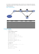
Network requirements
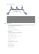
The CEs are connected to the PEs through serial interfaces and PPP encapsulation is used at the link layer.
Create two Martini VCs between CE 1 and CE 2, one is CE 1 – PE 1 – PE 2 – CE 2 (the primary VC) and
the other is CE 1 – PE 1 – PE 3 – CE 2 (the backup VC).