
R2511-HP MSR Router Series MPLS Configuration Guide(V5)


78
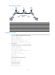
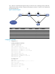
CE 1 and CE 2 communicate through the primary VC when this VC is operating correctly. When PE 1
detects that the primary VC fails, it brings up the backup VC so that CE 1 and CE 2 can communicate
through the backup VC.
Figure 31 Network diagram
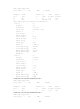
Device Interface IP address
Device
Interface
IP address
CE 1 S2/0 100.1.1.1/24
PE 2
Loop0
2.2.2.2/32
S2/0 100.2.1.1/24 sub S2/0 12.1.1.2/24
S2/1 100.3.1.1/24
PE 3
Loop0
3.3.3.3/32
PE 1 Loop0 1.1.1.1/32
S2/0
13.1.1.3/24
S2/1 12.1.1.1/24 CE 2 S2/0 100.1.1.2/24
S2/2 13.1.1.1/24
S2/1
100.2.1.2/24
Configuration procedure
1. Configure CE 1:
# Assign IP address to interfaces.
<Sysname> system-view
[Sysname] sysname CE1
[CE1] interface serial 2/0
[CE1-Serial2/0] link-protocol ppp
[CE1-Serial2/0] ip address 100.1.1.1 24
[CE1-Serial2/0] ip address 100.2.1.1 24 sub
[CE1-Serial2/0] quit
[CE1] interface serial 2/1
[CE1-Serial2/1] link-protocol ppp
[CE1-Serial2/1] ip address 100.3.1.1 24
[CE1-Serial2/1] quit
# Configure IS-IS.
[CE1] isis 1
[CE1-isis-1] network-entity 10.0000.0000.0001.00
[CE1-isis-1] quit
[CE1] interface serial 2/0
[CE1-Serial2/0] isis enable 1
[CE1-Serial2/0] quit
Loop0 Loop0
CE 1 CE 2PE 1 PE 2
S2/1 S2/0
Loop0
PE 3
S2/1 S2/0
S2/1
S2/2
S2/0
S2/0
S2/0
S2/1
S2/1
100.3.1.0/24