
R2511-HP MSR Router Series MPLS Configuration Guide(V5)
88
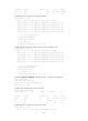
Verifying the configuration
# Verify that a VC has been established on PE 1.
[PE1] display mpls l2vc
Total ldp vc : 1 1 up 0 down 0 blocked
Transport Client VC Local Remote
VC ID Intf State VC Label VC Label
101 S2/0 up 1024 1032
# Verify that a VC has been established on PE 2.
[PE2] display mpls l2vc
Total ldp vc : 1 1 up 0 down 0 blocked
Transport Client VC Local Remote
VC ID Intf State VC Label VC Label
101 Eth1/1 up 1032 1024
# Verify that CE 1 and CE 2 can ping each other.
[CE1] ping 100.1.1.2
PING 100.1.1.2: 56 data bytes, press CTRL_C to break
Reply from 100.1.1.2: bytes=56 Sequence=1 ttl=255 time=30 ms
Reply from 100.1.1.2: bytes=56 Sequence=2 ttl=255 time=60 ms
Reply from 100.1.1.2: bytes=56 Sequence=3 ttl=255 time=50 ms
Reply from 100.1.1.2: bytes=56 Sequence=4 ttl=255 time=40 ms
Reply from 100.1.1.2: bytes=56 Sequence=5 ttl=255 time=70 ms
--- 100.1.1.2 ping statistics ---
5 packet(s) transmitted
5 packet(s) received
0.00% packet loss
round-trip min/avg/max = 30/50/70 ms
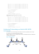
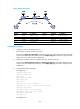
Configuring Kompella MPLS L2VPN
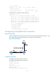
Network requirements
CEs are connected to PEs through Serial interfaces. The link layer encapsulation protocol is PPP.
Establish a Kompella VC, so CE 1 and CE 2 can exchange Layer 2 packets across the backbone.