
R2511-HP MSR Router Series MPLS Configuration Guide(V5)

89
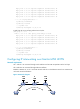
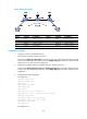
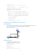
Figure 33 Network diagram
Device Interface IP address
Device
Interface
IP address
CE 1 S2/0 30.1.1.1/24 CE 2 S2/0 30.1.1.2/24
PE 1 Loop0 1.1.1.9/32
P
Loop0
2.2.2.9/32
POS5/1 168.1.1.1/24
POS5/0
168.1.1.2/24
PE 2 Loop0 3.3.3.9/32 POS5/1 169.1.1.1/24
POS5/0 169.1.1.2/24
Configuration procedure
1. Configure an IGP on the MPLS backbone.
This example uses OSPF. (Details not shown.)
# Execute the display ip routing-table command on each LSR to verify that the LSR has learned the
routes to the LSR IDs of the other LSRs. Execute the display ospf peer command to verify that OSPF
adjacencies in Full state have been established.
2. Configure basic MPLS and LDP to establish LDP LSPs. (Details not shown.)
# Execute the display mpls ldp session and display mpls ldp peer commands to display the LDP
sessions and peer relationship established, or the display mpls lsp command to display the LSPs
established.
3. Configure BGP L2VPN capability:
# Configure PE 1.
<Sysname> system-view
[Sysname] sysname PE1
[PE1] l2vpn
[PE1-l2vpn] mpls l2vpn
[PE1-l2vpn] quit
[PE1] bgp 100
[PE1-bgp] peer 3.3.3.9 as-number 100
[PE1-bgp] peer 3.3.3.9 connect-interface loopback 0
[PE1-bgp] l2vpn-family
[PE1-bgp-af-l2vpn] policy vpn-target
[PE1-bgp-af-l2vpn] peer 3.3.3.9 enable
[PE1-bgp-af-l2vpn] quit
[PE1-bgp] quit
# Configure PE 2.