
R2511-HP MSR Router Series Network Management and Monitoring Configuration Guide(V5)

139
Square sum of SD delay: 483202 Square sum of DS delay: 973651
SD lost packet(s): 0 DS lost packet(s): 0
Lost packet(s) for unknown reason: 0
Voice scores:
Max MOS value: 4.38 Min MOS value: 4.38
Max ICPIF value: 0 Min ICPIF value: 0
DLSw operation configuration example
Network requirements
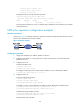
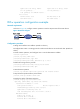
As shown in Figure 48, configure a DLSw operation to test the response time of the DLSw device.
Figure 48 Network diagram
Configuration procedure
# Assign each interface an IP address. (Details not shown.)
# Configure static routes or a routing protocol to make sure the devices can reach each other. (Details not
shown.)
# Create a DLSw operation, and configure 10.2.2.2 as the destination IP address.
<DeviceA> system-view
[DeviceA] nqa entry admin test1
[DeviceA-nqa-admin-test1] type dlsw
[DeviceA-nqa-admin-test1-dlsw] destination ip 10.2.2.2
# Enable the saving of history records.
[DeviceA-nqa-admin-test1-dlsw] history-record enable
[DeviceA-nqa-admin-test1-dlsw] quit
# Start the DLSw operation.
[DeviceA] nqa schedule admin test1 start-time now lifetime forever
# Stop the DLSw operation after a period of time.
[DeviceA] undo nqa schedule admin test1
# Display the results of the DLSw operation.
[DeviceA] display nqa result admin test1
NQA entry (admin admin, tag test1) test results:
Destination IP address: 10.2.2.2
Send operation times: 1 Receive response times: 1
Min/Max/Average round trip time: 19/19/19
Square-Sum of round trip time: 361
Last succeeded probe time: 2011-11-22 10:40:27.7
Extended results:
Packet loss in test: 0%
Failures due to timeout: 0
Failures due to disconnect: 0