
R2511-HP MSR Router Series Network Management and Monitoring Configuration Guide(V5)

40
NTP configuration examples
NTP client/server mode configuration example
Network requirements
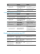
Perform the following configurations to synchronize the time between Device B and Device A:
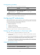
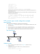
• As shown in Figure 17, the loc
al clock of Device A is to be used as a reference source, with the
stratum level 2.
• Device B operates in client/server mode and Device A is to be used as the NTP server of Device B.
Figure 17 Network diagram
Configuration procedure
1. Set the IP address for each interface as shown in Figure 17. (Details not shown.)
2. Configure Device A:
# Specify the local clock as the reference source, with the stratum level 2.
<DeviceA> system-view
[DeviceA] ntp-service refclock-master 2
3. Configure Device B:
# Display the NTP status of Device B before clock synchronization.
<DeviceB> display ntp-service status
Clock status: unsynchronized
Clock stratum: 16
Reference clock ID: none
Nominal frequency: 64.0000 Hz
Actual frequency: 64.0000 Hz
Clock precision: 2^7
Clock offset: 0.0000 ms
Root delay: 0.00 ms
Root dispersion: 0.00 ms
Peer dispersion: 0.00 ms
Reference time: 00:00:00.000 UTC Jan 1 1900 (00000000.00000000)
# Specify Device A as the NTP server of Device B so that Device B synchronizes to Device A.
<DeviceB> system-view
[DeviceB] ntp-service unicast-server 1.0.1.11
# Display the NTP status of Device B after clock synchronization.
[DeviceB] display ntp-service status
Clock status: synchronized
Clock stratum: 3
Reference clock ID: 1.0.1.11
Nominal frequency: 64.0000 Hz
Actual frequency: 64.0000 Hz