HP MSR Router Series OAA Configuration Guide(V5) Part number: 5998-2033 Software version: CMW520-R2511 Document version: 6PW103-20140128
Legal and notice information © Copyright 2014 Hewlett-Packard Development Company, L.P. No part of this documentation may be reproduced or transmitted in any form or by any means without prior written consent of Hewlett-Packard Development Company, L.P. The information contained herein is subject to change without notice.
Contents Configuring OAP modules ·········································································································································· 1 Overview············································································································································································ 1 Logging in to the operating system of an OAP module ································································································ 1 Swit
Configuring OAP modules The following matrix shows the feature and router compatibility: Hardware OAP module OAA MSR900 No. No. MSR93X No. No. MSR20-1X No. Yes. MSR20 No. No. MSR30 Yes. Yes. MSR50 Yes. Yes. MSR1000 No. No. Overview The HP Open Application Architecture (OAA) provides an open interface for third-party vendors to develop value-added applications (such as firewall and IPS) and integrate the applications into HP products.
Logging in through the management Ethernet port of the OAP module by using SSH or Telnet To log in to the operating system of an OAP module through its management Ethernet port, you must first configure the OAP module as the SSH server or Telnet server. To do so, follow these steps: 1. Switch to the CLI of the OAP module from the device, enable the SSH or Telnet server function, and configure the accounts for SSH or Telnet logins. 2.
Task Command Reset the OAP module.
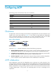
Configuring ACFP The following matrix shows the feature and router compatibility: Hardware ACFP MSR900 Yes. MSR93X No. MSR20-1X Yes. MSR20 No. MSR30 Yes. MSR50 Yes. MSR1000 No. Overview The Application Control Forwarding Protocol (ACFP) is designed based on the OAA architecture and operates in the server/client model (see Figure 1).
ACFP traffic management ACFP collaboration provides a mechanism that enables the ACFP client to manage the traffic on the ACFP server by implementing the following functions: • Mirroring and redirecting the traffic on the ACFP server to the ACFP client. • Permitting/denying the traffic from the ACFP server. • Restricting the rate of the traffic on the ACFP server. • Carrying the context ID in a packet to enable the ACFP server and ACFP client to communicate the packet context with each other.
• Supported context ID type—VLANID-context (carrying VLAN ID as the context ID). The location of the context ID in the packet depends on the ACFP server. ACFP server information indicates the collaboration capabilities of an ACFP server. ACFP clients can access this information through a collaboration protocol or collaboration MIB.
• Filtering rules—Used to determine which packets to deny and which packets to permit. Rule actions include deny and permit. • Restricting rules—Used to determine the rate at which packets are to be restricted. The rule action is rate. Rule information is described as follows: • ClientID—ACFP client identifier. • Policy index • Rule index—Rule identifier. • Status—Whether the rule is applied successfully. • Action—Rule action: mirror, redirect, deny, permit, or rate limit.
You can use the collaboration policy to manage the collaboration rules that belong to it. ACFP usage guidelines • In a GRE tunneling environment, an ACFP policy can be configured on a tunnel interface only. • ACFP does not support policy-based routing services or NetStream services. • The handling of the packets that are redirected by ACFP and the part of the QoS processing (FR-DE matching, ATM-CLP matching, inbound interface matching, QoS local-id, local precedence, and so on) are mutually exclusive.
Table 1 ACFP trap message level Trap message Level Context ID type changed Notifications ACFP client registration Notifications ACFP client deregistration Notifications ACSEI detects that ACFP client had no response Warnings ACFP server does not support the working mode of the ACFP client Errors Expiration period of ACFP collaboration policy changed Notifications ACFP collaboration rules are created Informational ACFP collaboration rules are removed Informational ACFP collaboration rules f
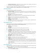
Task Command Remarks Display ACFP rule configuration information. display acfp rule-info { in-interface [ interface-type interface-number ] | out-interface [ interface-type interface-number ] | policy [ client-id policy-index ] } [ | { begin | exclude | include } regular-expression ] Available in any view. Display ACFP rule cache configuration information.
2. Use a MIB browser to configure a collaboration policy to redirect traffic arriving at interface Ethernet 1/2 to the ACFP client: a. Set the value of the node hh3cAcfpClientRowStatus to 4 to create an ACFP client with the index 1, and set the value of the node hh3cAcfpClientMode to 1 to enable working mode redirect for the client. b. Set the node hh3cAcfpPolicyRowStatus to 4 to create an ACFP policy and assign index 1.
Configuring ACSEI The following matrix shows the feature and router compatibility: Hardware ACSEI MSR900 Yes. MSR93X No. MSR20-1X Yes. MSR20 No. MSR30 Yes. MSR50 Yes. MSR1000 No. Overview HP ACFP Client and Server Exchange Information (ACSEI) provides a method for exchanging information between an ACFP server and its ACFP clients. As a supporting protocol for ACFP collaboration, ACSEI makes sure an ACFP server can cooperate with its ACFP clients to provide services.
Hardware Maximum number of concurrent ACFP clients MSR900 1. MSR20-1X 1. 1 on MSR30-11E, 30-11F, and 30-16. MSR30 6 on MSR30-10, 30-20, 30-40, and 30-60. MSR50 6. ACSEI timers An ACSEI server uses two timers, which can be set at the CLI: • Clock synchronization timer—Used to periodically trigger the ACSEI server to send clock synchronization advertisements to the ACSEI clients.
Step Command Remarks Optional. 6. Close an ACSEI client. acsei client close client-id This command is available only for an ACSEI client that is running on a Linux operating system. 7. Restart an ACSEI client. acsei client reboot client-id Optional. Displaying ACSEI client information on the server side Task Command Remarks Display ACSEI client summary. display acsei client summary [ client-id ] [ | { begin | exclude | include } regular-expression ] Available in any view.
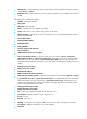
Changing the default startup setting for the ACSEI client The ACSEI client is enabled automatically after it is installed, and by default, the ACSEI client starts up when the OAP module starts up. You can configure the system to start or not to start the ACSEI client with the startup of the OAP module through either the CLI or GUI of the Linux operating system.
Figure 4 Service interface for the ACSEI client default startup 3. Move the cursor to acseid, and press the spacebar to specify one of the following options: { [ * ]—Automatically starts up the ACSEI client at startup. { [ ]—Does not automatically start up the ACSEI client at startup. 4. Press the Tab key to move the cursor to OK and press Enter to return to the previous view. 5. Select Quit to quit the setup interface.
Task Command Display ACSEI client debugging. acsei-client debug show Disable ACSEI client debugging.
Support and other resources Contacting HP For worldwide technical support information, see the HP support website: http://www.hp.
Conventions This section describes the conventions used in this documentation set. Command conventions Convention Description Boldface Bold text represents commands and keywords that you enter literally as shown. Italic Italic text represents arguments that you replace with actual values. [] Square brackets enclose syntax choices (keywords or arguments) that are optional. { x | y | ... } Braces enclose a set of required syntax choices separated by vertical bars, from which you select one.
Network topology icons Represents a generic network device, such as a router, switch, or firewall. Represents a routing-capable device, such as a router or Layer 3 switch. Represents a generic switch, such as a Layer 2 or Layer 3 switch, or a router that supports Layer 2 forwarding and other Layer 2 features. Represents an access controller, a unified wired-WLAN module, or the switching engine on a unified wired-WLAN switch. Represents an access point.
Index ACDELOR A E ACFP configuration example,10 Enabling the ACFP server on the device,8 ACFP configuration task list,8 Enabling the ACFP trap function on the device,8 C L Configuring the ACFP client (the OAP module),8 Configuring the ACSEI client on an OAP module,14 Logging in to the operating system of an OAP module,1 Configuring the ACSEI server,13 O Contacting HP,18 Overview,1 Conventions,19 Overview,12 D Overview,4 Displaying ACSEI client information on the server side,14 R Related i