
R2511-HP MSR Router Series Security Configuration Guide(V5)


348
Ste
p
Command
Remarks
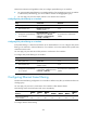
1. Enter system view.
system-view N/A
2. Enter interface view.
interface interface-type
interface-number
N/A
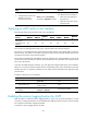
3. Configure Ethernet frame
filtering for the
inbound/outbound direction
of interface and set the
number of the ACL to be used.
firewall ethernet-frame-filter
{ acl-number | name acl-name }
{ inbound | outbound }
No filtering is performed by
default.
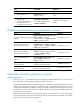
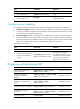
Displaying and maintaining a packet-filter firewall
Task Command
Remarks
Display the Ethernet frame filtering
statistics.
display firewall ethernet-frame-filter { all |
dlsw | interface interface-type
interface-number } [ | { begin | exclude |
include } regular-expression ]
Available in any view.
Display the packet filtering
statistics of the IPv4 firewall.
display firewall-statistics { all |
fragments-inspect | interface interface-type
interface-number } [ | { begin | exclude |
include } regular-expression ]
Available in any view.
Display the packet filtering
statistics of the IPv6 firewall.
display firewall ipv6 statistics { all |
interface interface-type interface-number }
[ | { begin | exclude | include }
regular-expression ]
Available in any view.
Clear the ACL-based firewall
statistics.
reset firewall ethernet-frame-filter { all |
dlsw | interface interface-type
interface-number }
Available in user view.
Clear the packet filtering statistics
of the IPv4 firewall.
reset firewall-statistics { all | interface
interface-type interface-number }
Available in user view.
Clear the packet filtering statistics
of the IPv6 firewall.
reset firewall ipv6 statistics { all | interface
interface-type interface-number }
Available in user view.
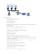
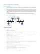
Packet-filter firewall configuration example
Network requirements
As shown in Figure 112, the internal network of a company is connected to Ethernet 1/1 of the router, and
the internal users access the Internet through Serial 2/0 of the router.
The company provides WWW, FTP and Telnet services to the outside. The internal subnet of the company
is 129.1.1.0, on which the internal FTP server address is 129.1.1.1, the Telnet server address is 129.1.1.2,
and the internal WWW server address is 129.1.1.3. The public address of the company is 20.1.1.1. NAT
is enabled on the router so that hosts on the internal network can access the Internet and external hosts
can access the internal servers.
Configure the firewall feature so that only specific users on external networks can access the internal
servers, and that only specific hosts on the internal network can access external networks. This example
permits access of the external user at 20.3.3.3.