HP MSR Router Series Terminal Access Configuration Guide(V5) Part number: 5998-2022 Software version: CMW520-R2511 Document version: 6PW103-20140128
Legal and notice information © Copyright 2014 Hewlett-Packard Development Company, L.P. No part of this documentation may be reproduced or transmitted in any form or by any means without prior written consent of Hewlett-Packard Development Company, L.P. The information contained herein is subject to change without notice.
Contents Configuring terminal access ········································································································································ 1 Overview············································································································································································ 1 Terminal access types ···································································································································
Configuration prerequisites ·································································································································· 66 Modifying system configuration file ttydefs ········································································································ 67 Editing ttyd configuration file ······························································································································· 67 Modifying route configuration file
Setting the terminal timeout disconnection timer ································································································ 94 Configuring manual link disconnection ·············································································································· 94 Enabling encryption ·············································································································································· 95 Configuring source address binding ··········
Configuring terminal access NOTE: The HP MSR900, and MSR93X (except the JG514A, JG515A and JG531A) routers do not support interface modules and thus cannot provide terminal access through an asynchronous serial port module. Overview Terminal access enables a terminal to use an asynchronous interface to access a front-end processor (FEP) or another terminal through a router.
establishing a connection between the initiator and the receiver. Each terminal supports up to eight virtual type terminals (VTYs) using these access types, and supports switchover between the VTYs. RTC terminal access is used to monitor terminal data. It is initiated by a router and received by another router. Only RTC terminal access supports UDP connections with synchronous terminals. Support for features depends on the terminal access type.
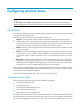
The monitoring terminal at the data center and the monitored terminal are each connected to a different router through a serial interface, and the routers exchange data with each other through an IP network. Normally, the router connected to the monitoring device acts as the terminal access initiator (the RTC client). The monitoring device is always ready to initiate a connection request at any time to access the data on the monitored device.
The orange dotted line represents RTC terminal access. Router B acts as an RTC client and Router A as the RTC server. Router B initiates monitoring requests and Router A, upon receiving a monitoring request, sends the data from the monitored terminal to the monitoring device through Router B, to implement terminal monitoring. Terminal access feature list The following table lists the features of terminal access.
Feature Supported by Description TCP buffer parameter configuration TTY, Telnet, TCP_11_Client, TCP_11_Server, TCP_N1_Server, ETelnet, SSH N/A Terminal buffer parameter configuration TTY, Telnet, TCP_11_Client, TCP_11_Server, TCP_N1_Server, ETelnet, SSH N/A Threshold for VTY switching failure times TCP_11_Client N/A Receiver VTY switching rules TCP_11_Server N/A RTC terminal authentication TCP_11_Client, TCP_11_Server N/A Terminal access TTY, Telnet, TCP_11_Client, TCP_11_Server, UDP_11_C
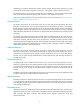
Figure 2 Terminal access network Source address binding The principle of source IP address binding is to configure an IP address on a stable interface (the loopback interface or dialer interface is recommended) and use this address as the source IP address of the upstream TCP connection from the router through IP unnumbered configuration. If an FEP runs, the IP address of the router connected to the FEP needs to be authenticated.
INPUT YOUR CHOICE: Pressing any key to return When the following events happen, this feature enables the terminal to display an error message, and you can press any key to return to the menu interface: • An invalid menu option is entered. • The FEP providing the service you select is unreachable. • A connection is terminated. Fast VTY service switching The characteristics of banking services require each bank branch to provide services such as deposit and corporate services.
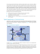
As shown in Figure 3, data is transmitted in ciphertext between Router A and the FEP. Router A and the FEP that runs the program ttyd/ccbtelnetd/sshd are responsible for data encryption and decryption. At present, the supported encryption algorithms are as follows: • Advanced encryption standard (AES) encryption is supported by TTY terminal access. • AES and RC4 encryption are supported by ETelnet terminal access. • RSA and DSA encryption are supported by SSH terminal access.
• A FEP can send the saved screen contents to a terminal when the screen is switched or redrawn on the terminal. • A router can send the saved screen contents to the terminal upon receiving control characters for switching or redrawing the screen from a terminal. The screen saving function of a terminal, FEP, or router varies. The screen saving function of a router supports Telnet, ETelnet, and SSH.
You can set some parameters of TCP connection, including the receive buffer size, send buffer size, non-delay attribute, keepalive interval and transmission times. Terminal buffer parameter configuration You can set parameters for the terminal buffer, including whether to clear the buffer before receiving data, receive buffer size, send buffer threshold, and the maximum size of data to be sent to the terminal at one time.
UDP RTC one-to-one transparent transmission This mode is mainly applied to voice transmission. TCP RTC transparent transmission has a certain forwarding delay, and is not suitable for voice communications. Because the voice service does not require high reliability, voice data can be transmitted through UDP. This mode provides one-to-one transmission in synchronous mode, but does not support asynchronous mode.
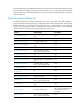
Number Item Description 1 Maximum number of TTYs 255. This number is subject to the number of router interfaces available for terminal access. 2 Maximum number of APPs 2040. 3 Maximum number of VTYs supported by each TTY 8. 4 Maximum number of peer terminals supported by UDP_1N_Server 10.
• Advanced configuration commands—Used for implementing the extended functions of terminal access. • Display and maintenance commands—Used for displaying and debugging terminal access. The configuration commands can be classified into the commands available in user view, system view, template view, and interface view. Most important configurations of the terminal access system are performed in templates. You can save a series of router parameter configurations into a template.
Step Command Remarks 1. Enter system view. system-view N/A 2. Enable terminal access on the router. rta server enable Disabled by default. 3. Create a terminal template and enter terminal template view. rta template template-name N/A 4. Configure a TTY VTY. vty vty-number tty remote ip-address port-number [ source source-ip ] After this configuration, Telnet VTYs can be configured in this template, but RTC client VTYs or RTC server VTYs cannot. 5. Exit terminal template view.
Advanced TTY initiator configuration When you configure advanced TTY initiator settings, follow these guidelines: • If both the global source IP address and the source IP address for a VTY are configured, the source IP address for the VTY is used. • Configure TCP parameters before establishing a TCP connection. If you configure the parameters after a TCP connection is established, the TCP connection must be re-established for the parameters to take effect.
Step Command Remarks 11. Enable terminal data read blocking. data read block 12. Configure the terminal data send delay. data send delay milliseconds Optional. Disabled by default. Optional. 0 milliseconds by default. That is, there is no send delay. Optional. 13. Configure the router to not clear the terminal receive buffer after the TCP connection is established. driverbuf save 14. Configure the terminal receive buffer size. driverbuf size size 15. Enable filtering of flow control characters.
Step Command Remarks 25. Configure the maximum size of data to be sent to a terminal at one time. sendbuf bufsize size 26. Configure the terminal send buffer threshold. sendbuf threshold value 27. Configure the connectivity test hotkey. testkey ascii-code&<1-3> Optional. 500 bytes by default. Optional. Not configured by default. Optional. Not configured by default. Optional. 28. Configure TCP parameters. tcp { keepalive time count | nodelay | recvbuf-size recvsize | sendbuf-size sendsize } 29.
Figure 4 Network diagram Configuring the initiator (router) Perform the following configuration in TTY one-to-one mode: # Enable terminal access. system-view [Sysname] rta server enable # Create a template and enter template view. [Sysname] rta template temp1 # Configure a VTY application. [Sysname-rta-template-temp1] vty 0 tty remote 1.1.254.77 9010 [Sysname-rta-template-temp1] quit # Configure the Ethernet interface. [Sysname] interface ethernet 0/0 [Sysname-Ethernet0/0] ip address 1.1.247.
[Sysname-Async1/3] async mode flow [Sysname-Async1/3] rta terminal temp1 4 # Configure software flow control. [Sysname] user-interface tty 17 20 [Sysname-ui-tty17-20] flow-control software Configuring the receiver (Unix server) Perform the following configuration by referring to "Installing and configuring an FEP." The following uses SCO OpenServer Unix as an example. 1. Edit the file /etc/ttyd.conf. serverport 9010 mode 1 ttyp40 2.2.2.1 1 ttyp41 2.2.2.1 2 ttyp42 2.2.2.1 3 ttyp43 2.2.2.1 4 2.
Step Command Remarks Create a terminal template and enter terminal template view. rta template template-name N/A 4. Configure a Telnet VTY. vty vty-number telnet remote ip-address [ port-number ] [ source source-ip ] After this configuration, the template can be configured with Telnet VTYs, but not RTC client VTYs or RTC server VTYs. 5. Exit terminal template view. quit N/A 6. Enter interface view.
• Configure the receive buffer size before applying the terminal template. If you configure the receive buffer size after a terminal template is applied, you must remove the application of the terminal template and apply the terminal template again for the receive buffer size to take effect. • The ASCII value of the hotkey must be different from the ASCII value of any other hotkey configured on the device. Otherwise, hotkey conflicts occur.
Step 13. Configure the TCP connection idle timeout time. Command Remarks Optional. idle-timeout seconds 0 seconds by default. That is, the connection never times out. Optional. 14. Configure the menu hotkey. menu hotkey ascii-code&<1-3> 15. Configure a screen code for the menu screen. menu screencode string 16. Enable printing of terminal connection information on the terminal. 17. Enable the router to print information on the terminal. Not configured by default.
Step Command Remarks 26. Configure a screen code for a VTY screen. vty vty-number screencode string 27. Configure the VTY switching hotkey. vty vty-number hotkey ascii-code&<1-3> 28. Enable screen saving. screen save enable 29. Set the terminal screen display size. screen-size height height-in-characters width width-in-characters 30. Configure the terminal type. terminal type { vt100 | vt220 } Optional. Not configured by default. Optional. Not configured by default. Optional.
Configuration procedure 1. Configure the initiator: # Enable terminal access. system-view [Sysname] rta server enable # Create a terminal template and enter terminal template view. [Sysname] rta template temp2 # Configure VTY 0. [Sysname-rta-template-temp2] vty 0 telnet remote 10.110.96.53 [Sysname-rta-template-temp2] vty 0 description chuxu # Configure the screen saving code for the VTY 0. [Sysname-rta-template-temp2] vty 0 screencode \E!8Q # Configure the hotkey for VTY 0 as Alt+A.
The receivers of Telnet terminal access are FEPs. An FEP only needs to run the Telnet server program and the corresponding application program. There is no need to modify or compile the Unix kernel. Configuring ETelnet terminal access Configuring the ETelnet initiator Basic ETelnet initiator configuration Step Command Remarks 1. Enter system view. system-view N/A 2. Enable terminal access on the router. rta server enable Disabled by default. 3.
Step Command Remarks By default, the flow control mode is none. That is, no flow control is implemented. 11. Enable software flow control of data on the current user interface. For more information about the flow-control software command, see the flow-control command in Fundamentals Command Reference.
Step Command Remarks Optional. 6. Configure the automatic link establishment time. auto-link time 7. Bind a VPN instance. bind vpn-instance vpn-name 8. Enable terminal data read blocking. data read block Configure the terminal data send delay. data send delay milliseconds 9. 0 seconds by default. That is, no automatic link establishment is performed. Optional. Not configured by default. Optional. Disabled by default. Optional. 0 milliseconds by default. That is, there is no send delay.
Step Command Remarks 19. Configure the print language. print language { chinese | english } Optional. 20. Set the terminal reset hotkey. resetkey ascii-code&<1-3> 21. Configure the maximum size of data to be sent at one time. sendbuf bufsize size 22. Configure the terminal send buffer threshold. sendbuf threshold value 23. Set the terminal connectivity test hotkey. testkey ascii-code&<1-3> Chinese by default. Optional. Not configured by default. Optional. 500 bytes by default. Optional.
ETelnet terminal access configuration example Network requirements As shown in Figure 6, two Unix FEPs use IP addresses 10.110.96.53 and 10.110.96.54 and use the port number 2080. A terminal is used at the outlet. On the terminal, the first VTY corresponds to FEP 1, with the VTY switching hotkey of < Alt+A >. The second VTY corresponds to FEP 2, with the VTY switching hotkey Alt+B and the menu hotkey Alt+C. Figure 6 Network diagram Receiver Initiator FEP 1 10.111.0.1/24 10.110.96.
[Sysname] interface async 1/0 [Sysname-Async1/0] async mode flow [Sysname-Async1/0] rta terminal temp2 3 [Sysname-Async1/0] quit # Configure software flow control. [Sysname] user-interface tty 17 [Sysname-ui-tty17] flow-control software After performing the above configurations, you will see the following menu on the terminal. (You can enter an option on the display or exit by pressing .) TTY ACCESS SYSTEM VERSION 3.0 1. SELECT VTY(0): chuxu 2. SELECT VTY(1): duigong 0. QUIT INPUT YOUR CHOICE: 2.
Step 7. Command Configure the asynchronous serial interface to operate in flow mode. async mode flow Remarks By default, an asynchronous serial interface operates in the protocol mode and an AUX interface the flow mode. For more information about the async mode flow command, see the async mode command in Interface Command Reference. 8. Apply the template to the interface.
To configure advanced SSH initiator settings: Step Command Remarks N/A 1. Enter system view. system-view 2. Configure the global source IP address of TCP connections. rta source-ip ip-address Enable pressing any key to return. rta vty-style smart 4. Enter terminal template view. rta template template-name 5. Configure the automatic link teardown time. 6. Configure the automatic link establishment time. auto-link time 7. Bind a VPN instance. bind vpn-instance vpn-name 8.
Step Command Remarks Optional. 16. Enable printing terminal connection information on the terminal. print connection-info 17. Configure the router to print information on the terminal. print information By default, terminal connection information is printed on the terminal. You must use the print information command before using this command. Optional. By default, the router prints information on the terminal. Optional. 18. Enable printing of menu information on the terminal. print menu 19.
Step Command Remarks 30. Configure the terminal type. terminal type { vt100 | vt220 } Optional. vt100 by default. Optional. 31. Update the configuration. update changed-config If you modify the terminal template that has been applied to an interface, use this command to apply the latest configuration. Executing this command will disconnect connections. Make sure critical services are not affected. Configuring the SSH receiver The receiver of SSH terminal access is an FEP.
# Configure VTY 0. [Sysname-rta-template-temp2] vty 0 ssh remote 10.110.96.53 [Sysname-rta-template-temp2] vty 0 description chuxu # Configure the screen saving code for VTY 0. [Sysname-rta-template-temp2] vty 0 screencode \E!8Q # Configure the switching hotkey for VTY 0 as Alt+A. [Sysname-rta-template-temp2] vty 0 hotkey 1 96 13 # Configure VTY 1. [Sysname-rta-template-temp2] vty 1 ssh remote 10.110.96.
Basic RTC initiator configuration Step Command Remarks 1. Enter system view. system-view N/A 2. Enable terminal access on the router. rta server enable Disabled by default. 3. Create a terminal template and enter terminal template view. rta template template-name N/A 4. Create a TCP RTC client VTY. vty vty-number rtc-client remote ip-address port-number [ source source-ip ] After this configuration, the template cannot be configured with any TTY, Telnet, or RTC server VTYs. 5.
Step Command 12. Enable software flow control of data on the current user interface. Remarks By default, the flow control mode is none. That is, no flow control is implemented. For more information about the flow-control software command, see the flow-control command in Fundamentals Command Reference.
Step Command Remarks Optional. 6. Configure the automatic link establishment time. auto-link time 7. Bind a VPN instance to the template. bind vpn-instance vpn-name Enable terminal data read blocking. data read block Configure the data send delay. data send delay milliseconds 8. 9. Optional. Not configured by default. Optional. Disabled by default. Optional. 0 milliseconds by default. That is, there is no send delay. Optional. 10.
Step Command Remarks Optional. 19. Configure TCP parameters. tcp { recvbuf-size recvsize | sendbuf-size sendsize | nodelay | keepalive time count } By default, the receive buffer size is 2048 bytes, the send buffer size is 2048 bytes, delay is enabled, the keepalive interval is 50 seconds, and the keepalive number is 3. 20. Configure the password for VTY authentication. vty vty-number password { simple | cipher } string Optional. 21. Configure a screen code for the VTY screen.
Step Command Remarks 7. Enter interface view. interface interface-type interface-number The interface type must be supported by terminal access. Synchronous and asynchronous interfaces are supported. 8. Configure the asynchronous serial interface to operate in flow mode. async mode flow Configure the protocol type of the synchronous serial interface as HDLC. link-protocol hdlc 9. Use either command.
• The TCP parameters must be configured before a TCP connection is established. If you configure the parameters after a TCP connection is established, the TCP connection must be re-established for the parameters to take effect. You can press the reset hotkey on the terminal to re-establish the TCP connection. • Configure the receive buffer size before a terminal template is applied.
Step Command Remarks Optional. 13. Enable printing of terminal connection information on the terminal. print connection-info 14. Configure the router to print information on the terminal. print information By default, the router prints information on the terminal. 15. Configure the print language. print language { chinese | english } Optional. 16. Configure the maximum size of data to be sent to a terminal at one time. sendbuf bufsize size 17. Configure the terminal send buffer threshold.
Step Command Remarks 2. Enable relay forwarding. rta relay enable Disabled by default. 3. Configure a TCP listening port. rta relay listen-port port-number Not configured by default. Optional. 4. Set the send buffer size and receive buffer size for TCP connections. rta relay tcp { recvbuf-size recvbuff-size | sendbuf-size sendbuff-size } By default, the send buffer size and the receive buffer size are 2048 bytes.
Step Command Remarks 2. Enable terminal access. rta server enable Disabled by default. 3. Create a terminal template and enter terminal template view. rta template template-name N/A 4. Create a UDP RTC client VTY. vty vty-number rtc-client remote ip-address remote-port remote-port-number udp [ local-port local-port-number ] [ source source-ip-address ] After this configuration, you cannot configure other types of VTYs in the template. 5. Return to system view. quit N/A 6.
Configuring the synchronous UDP RTC one-to-many receiver (UDP_1n_Server) The initiator is a UDP_11_Client, which is connected to the monitoring device through a synchronous serial interface. The receiver is a UDP_1N_Server, which is connected to the monitored device through a synchronous serial interface. An initiator can establish a UDP connection with a receiver at any time to obtain data.
Figure 8 Network diagram Configuration procedure 1. Configure the RTC server: # Enable terminal access. system-view [Sysname] rta server enable # Set the listening port of the server. [Sysname] rta rtc-server listen-port 9000 # Create a terminal template and enter terminal template view. [Sysname] rta template rtcserver # Configure the VTY. [Sysname-rta-template-rtcserver] vty 0 rtc-server remote 10.111.0.
Asynchronous RTC VPNs configuration example Network Requirements As shown in Figure 9, terminal CE A in the monitoring center and remote terminal CE B are in MPLS L3VPN VPNA and connected to the interface Async 1/0 on PE A and PE B respectively. Configure monitor CE B in real time through CE A. • The terminal numbers of PE A and PE B are 2. • The listening port of the RTC server is 9000. Figure 9 Network diagram Configuration procedure 1. Configure the RTC server: # Configure MPLS L3VPN.
2. Configure the RTC client: # Configure MPLS L3VPN. For more information, see MPLS Configuration Guide. # Bind Loopback 1 to VPNA. [PEA] interface loopback 1 [PEA-LoopBack1] ip address 169.254.2.1 32 [PEA-LoopBack1] ip binding vpn-instance vpna [PEA-LoopBack1] quit # Enable terminal access. [PEA] rta server enable # Configure a terminal template. [PEA] rta template rtcc # Configure VTY 0 on the RTC client. [PEA-rta-template-rtcc] vty 0 rtc-client remote 169.254.3.1 9000 # Bind VPNA to the template.
Configuration procedure 1. Configure TCP_11_Clients (Router A and Router C): # Enable terminal access. system-view [Sysname] rta server enable # Create a terminal template and enter terminal template view. [Sysname] rta template rtcclient # Configure the VTY. [Sysname-rta-template-rtcclient] vty 0 rtc-client remote 1.1.1.3 2000 # Apply the template to the interface. [Sysname] interface async 1/0 [Sysname-Async1/0] async mode flow [Sysname-Async1/0] rta terminal rtcclient 1 2.
# Create a terminal template and enter terminal template view. [Sysname] rta template rtcclient # Configure the VTY. [Sysname-rta-template-rtcclient] vty 0 rtc-client remote 1.1.1.3 3000 udp local-port 3001 source 1.1.1.1 [Sysname-rta-template-rtcserver] quit # Apply the template to the interface. [Sysname] interface Serial2/0 [Sysname-Serial2/0] link-protocol hdlc [Sysname-Serial2/0] rta terminal rtcclient 1 2. Configure the UDP_11_Server (Router B): # Enable terminal access relay.
Configuration procedure 1. Configure the UDP_11_Clients (Router A and Router C). See "UDP RTC one-to-one configuration example." 2. Configure the UDP_1N_Server (Router B): # Enable terminal access. system-view [Sysname] rta server enable # Create a terminal template and enter terminal template view. [Sysname] rta template rtcserver # Configure the VTY. [Sysname-rta-template-rtcserver] vty 0 rtc-multipeer 1.1.1.2 3000 # Configure the IP addresses and port numbers of the two initiators.
Installing and configuring an FEP To implement terminal access with an FEP as the receiver, the router-side program serving as the initiator must work together with the FEP-side programs serving as the server that receives connection requests from the initiator. This chapter covers the installation, configuration, operation, and management of FEP-side programs.
NOTE: File names are case-sensitive in Unix. Use the ls /mnt command to view file names before copying them. The ttyd, ttyadmcmd, and ttyadm programs are installed. NOTE: After completing the above-mentioned tasks, make sure you use the umount command to uninstall the floppy drive as follows: # cd / # umount /mnt Using FTP You can also use FTP to install the ttyd programs. The following describes the installation procedure using FTP on a Windows system. 1. Place the ttyd programs in a directory.
the ttyd, ttyadmcmd, and ttyadm programs to your SCO OpenServer Unix server. The installation procedure is as follows: 1. Copy the installation file VOL.000.000 to a directory on the SCO OpenServer Unix server. The following example assumes that the installation file is copied to the directory /build. Type scoadmin to open the SCO manager. 2. From [\File\Software Manager], select [\Software\Install New...] to enter software installation interface, and then select local installation. 3.
5. Change the value of "NSPTTYS: number of pseudo-ttys on system." to 256. 6. Compile the kernel and restart the server. Then, the maximum number of devices becomes 256. Modifying the maximum number of files a process can open By default, each SCO OpenServer Unix process can open up to 110 files. If a Unix server is to be connected to more than 50 terminals, change this number to 600. To do this, execute the following command: # /etc/conf/cf.
mode 1 Operating mode of the ttyd process. 0 indicates many-to-one mode, and 1 indicates TTY one-to-one mode. Currently, it must be set to 1. nodelay 1 Specifies the ttyd process to support (with a value of 1) or not to support (with a value of 0) the nodelay attribute. The default is 1, meaning that ttyd responds instantly upon receiving data from the peer. On low speed lines, this can improve the echoing speed.
of a pseudo terminal must be present in the /dev directory and must start with tty. To configure pseudo terminal names not to start with "tty", you must use a full path name starting with "/dev/". "accesstime 2 8:00-12:00 13:00-18:00" in the sample entry specifies that the terminal can be connected to the Unix server during two periods only: 8:00 to 12:00 and 13:00 to 18:00. Up to four access periods can be defined for a terminal. By default, no time restriction is imposed.
Running and terminating ttyd on Unix server Running ttyd CAUTION: With automatic link establishment function configured on the router, after you kill a child process and then use ps-ef, you may still find a process corresponding to the same pseudo terminal, which is actually a new process. You can run the ttyd program after installation and configuration.
• You can use the kill 8312 command to kill the ttyd child processes corresponding to the pseudo terminal ttyp40. Use the kill command, rather than the kill -9 command, to kill ttyd processes. Enabling ttyd autorun at system startup 1. Open the file /etc/init.d/ttyd. # vi /etc/init.d/ttyd 2. Add the following to the file: case "$1" in 'start') echo "Start ttyd ..." # To launch multiple configuration files, list each of them in a line. /etc/ttyd /etc/ttyd.conf ;; 'stop') echo "Stop ttyd ...
3 - View system resources. 4 - View router status. 5 - View statistics. 6 - Edit ttyd configuration file. 0 - Exit Enter: You can select a function by entering the corresponding number displayed on the screen. The following describe each of the functions.
Main process: Process No. Port No. Debugging level of bytes received from tty Number of bytes received from socket 12674 9998 0 2 57 6108 9022 3 8 69 Number Child process: Process NO. Parent process No. No. Debugging level 12676 3. 12674 ttyp55 tty device name 10.110.96.44 1219 Router IP 6 Port No. Terminal 0 Terminate a ttyd process. From the process management submenu, select option 3 to display all the ttyd processes running in the system.
{ Level 0—At this level, only error information is output. { Level 1—At this level, alarm information is output besides error information. { Level 2—At this level, prompt information is output besides error and alarm information. { Level 3—At this level, besides error, alarm, and prompt information, all the data read from and written to sockets and pseudo-terminals (PTYs) are output in the character format and in the hexadecimal format respectively. The default log output level is level 0.
Display system resources 1 - Display CPU resources. 2 - Display memory resources. 3 - Display stream resources. 0 - Return to the main menu. Enter: 1. Display CPU resources. From the system resource submenu, select option 1 to display the CPU resources in the system. This operation is the same as executing the sar -u 1 5 command. The following displays: SCO_SV sco2 3.2v5.0.
class 5, 1024 bytes class 6, 2048 bytes 32 class 7, 4096 bytes 171 170 class 8, 8192 bytes 5 0 class 274 0 182 9, 16384 bytes 2 0 class 10, 32768 bytes 0 0 class 11, 65536 bytes 0 class 12, 131072 bytes 0 29 0 6460 273 0 1 185 171 70 5 2 3 2 0 0 0 0 0 0 class 14, 524288 bytes 2734 5 0 0 0 class 13, 262144 bytes 32 92 0 0 0 0 0 0 0 0 0 0 0 0 0 0 0 0 0 0 0 0 total configured streams memory: 8000.00KB streams memory in use: 1103.
TTY Recv : 2219 Bytes TTY Send : 2336030 Bytes Last Recv Time : 21:59:11 Last Send Time : 21:59:11 --------------------Current VTY Recv : 2219 Bytes Current VTY Send : 2336030 Bytes Current APP Recv : 2327134 Bytes Current APP Send 3. : 2490 Bytes Display brief tty-server information. From the router status submenu, select option 3 to display the APP summary on the corresponding router. The following displays: APP_ID 4. PORT STATE APP_TYPE APP_NAME 1 10.110.96.
Total number of bytes read from socket: 4 Number of bytes last read from socket: 1 Time when socket was last read?2002-07-15 13:59:43 Total number of packets written to socket: 2 Total number of bytes written to socket: 116 Number of bytes last written to socket: 58 Time when socket was last written to? 2002-07-15 13:59:44 Total number of packets read from pty: 2 Total number of bytes read from pty: 116 Number of bytes last read from pty: 58 Time when pty was last read?2002-07-15 13:59:44 Total number of pa
7. Select [Advanced options]. 8. Select [Pseudo ttys]. The default value is 32. Change the value to 256. 9. Compile the kernel. # /etc/conf/bin/idbuild -B 10. Reboot the FEP. # init 6 Now, the system can support up to 256 pseudo terminals. You can also increase the number of pseudo terminals by installing the acp program and updating as follows: 11. Change the value of kernel parameter NUMSCOPT to 256. # /etc/conf/bin/idtune NUMSCOPT 256 12.
Modifying route configuration file The terminal access router is usually connected to the Unix server through WANs and therefore located on an IP segment different from that of the Unix server, in which case you must configure a route on the Unix server. The following example shows how to do this: # route add –netmask 255.255.255.0 –net 10.110.96.0 63.1.1.250 In the example above, 10.110.96.0 is the destination subnet, with the subnet mask of 255.255.255.0 and the next hop IP address of 63.1.1.250.
# vi /etc/system 2. Add "set npty=176" into the file: 3. Save your configuration and exit. 4. Create the file "reconfigure." # touch /reconfigure 5. Reboot the system. # reboot The number of supported pseudo terminals is now 176. Modifying the maximum number of files a process can open By default, each SUN OS process can open up to 64 files. If a Unix server is to be connected with a number of terminals (usually more than 50), change the value to 400.
Installing device drivers Using the floppy disk For more information, see "Using a floppy disk." Using FTP For more information, see "Using FTP." Configuration prerequisites Adding pseudo terminals When the number of pseudo terminals on the IBM AIX server is not enough, you can use the smit configuration program to add pseudo terminals as follows: 1. Launch smit. # smit 2. Select [Devices]. 3. Select [PTY]. 4. Select [Maximum number of BSD Pseudo-Terminals] and set it to 256.
Running and terminating ttyd on the Unix server Running ttyd For more information, see "Running and terminating ttyd on Unix server." Terminating ttyd For more information, see "Terminating ttyd." Enabling ttyd autorun at system startup Add the command for starting ttyd at the end of the file /etc/inittab. # vi /etc/inittab Append the following line: ttyd:23:wait:/etc/ttyd /etc/ttyd.
# ln /dev/ptym/ptyy0 /dev/ptyy0 Modifying the maximum number of processes supported by the system By default, the HP-UX server supports up to 664 processes. If a Unix server is to be connected with many terminals (usually more than 50), change the value to 2000. To do this, use the following commands: # sam After entering the menu interface, select [kernel configuration] to enter the submenu, and then select [configurable parameters] and change the value of [nproc] to 2000.
pid=`ps -ef | grep ttyd | awk '{if ($3 == 1) print $0}' | awk '{print $2}'` if [ ! "$pid" = "" ] then kill $pid fi ;; esac 3. Save your configuration and exit. 4. Link the file to the startup directory. # chmod u+x /sbin/init.d/ttyd # ln -s /sbin/init.d/ttyd /sbin/rc2.d/S99ttyd # ln -s /sbin/init.d/ttyd /sbin/rc2.d/K00ttyd Installing and using ttyd administration program ttyadm For more information, see "Installing and using ttyd administration program ttyadm.
data seg size (kbytes, -d) unlimited file size (blocks, -f) unlimited max locked memory (kbytes, -l) 4 max memory size (kbytes, -m) unlimited open files pipe size stack size cpu time max user processes virtual memory (-n) 2048 (512 bytes, -p) 8 (kbytes, -s) 10240 (seconds, -t) unlimited (-u) 4096 (kbytes, -v) unlimited Editing the ttyd configuration file For more information, see "Editing the ttyd configuration file.
Troubleshooting terminal access Prompts on terminals Number Prompt Description 1 (TTY tty-number: vty-number starting connect to server fail!) Creating a socket failed because, for example, no WAN IP address is configured on the router. 2 (TTY tty-number: vty-number fail to connect server-name!) The router failed to establish a TCP connection to the Unix server because, for example, the Unix server is turned on but ttyd is not running.
Number Prompt Description 14 (authentication failed, invalid TTY No.!) Authentication of a terminal failed. The terminal number is not identical to that configured in the ttyd configuration file on the Unix server. 15 (authentication failed, unknown error!) Authentication of a terminal failed. An unknown error occurred. Terminal access troubleshooting If you are having trouble with terminal access, the following sections might provide the solution.
Serial interfac e Asynchro nous serial interface DB-25 DB-9 RJ-45 (for telecom/banks) Signal Signal direction Signal description 5 8 8/7 CTS Æ Clear to send 6 6 7/3 DSR Æ Data set ready 3 2 6/5 RxD Æ Receive data 7 5 5/4 GND - Logical ground 8 1 4/1 DCD Æ Data carrier detect 2 3 3/6 TxD Å Transmit data 20 4 2/2 DTR Å Data terminal ready 4 7 1/8 RTS Å Request to send Terminal access converters are exclusively used for 8AS cables (RJ-45 for banks) and 16
software inbound) commands on the asynchronous serial interface to prevent detection of the dsr/dtr signals. This allows the asynchronous interface to automatically enter the up state, and prevents detection of hardware flow control signals by adopting software flow control or no flow control. When a 5-wire asynchronous serial interface cable is used, flow control signal lines are absent.
• Verify that the IP address and terminal number configured in ttyd.conf and those on the router are consistent. • If source IP address binding is configured on the router, verify that the source IP address can be pinged through from the Unix server Check whether the router has established a TCP connection with the Unix server 1. Verify TCP connectivity using the terminal connectivity test hotkey. In terminal access, a command is provided for testing terminal connectivity.
2. The inittab system file configuration is correct. X. For more information, see "View the debugging information of the router and ttyd program of the server." For a dumb terminal, check whether the pseudo terminal is activated A dumb terminal is a pseudo terminal that does not push the login interface. Check whether the banking service process has activated the pseudo terminal. If not, activate it.
Cause: The user was accessing the Unix server out of the defined periods. 13. Fail:Failed in opening pty5, out of devices Cause: Failed to find the device. 14. Fail:Failed in opening pty5, errno=5 Cause: Failed to open device pty5. The value of the errno parameter indicates the cause. 15. Fail:It failed in binding server,so it exited Cause: Another process is using the listening port number specified in the ttyd configuration file. 16.
Terminal access FAQs This chapter identifies and explains certain common problems that may occur, and how to solve them. If there are insufficient stream resources on the Unix server, modify kernel parameters If an FEP is connected to too many terminals, you must modify the Unix kernel of the FEP to increase stream resources to avoid insufficient stream resources during operation.
7. Exit to the level 2 interface and select [Relink Kernel] to recompile the kernel. 8. Exit scoadmin and reboot the Unix server. After reboot, the change takes effect. You can use the netstat -m command to view current system stream resources. The third line from the bottom of the command output will show that the total configured streams memory has been changed from 2048 KB to 8000 KB.
• For the third case, you must configure the corresponding device in the inittab file. • For the fourth case, you must configure the router and the Unix server to use the same application mode. Terminal echoing speed is low Use the ttyd administration program to check the system resource occupation rate of the Unix server. If the rate is relatively high, locate which service process is abnormal and, if necessary, kill the process.
Check whether the application mode is many-to-one, which may cause data for terminals to fall into confusion. Upgrade to a router version supporting TTY one-to-one mode and switch to TTY one-to-one application mode. Pressing menu switching hotkey cannot bring up the menu When a terminal is listing directories or outputting data, pressing the menu switching hotkey does not bring up the menu. Perform VTY switching when the terminal is idle.
Configuring IP terminal access This chapter describes how IP terminal access operates and how to configure IP terminal access. Overview IP terminal access allows a terminal to access a remote Unix or Linux server, which is also known as a front-end processor (FEP), through a router. The router acts as the initiator to forward data between the terminal and the Unix or Linux server that serves as the receiver.
Figure 15 IP terminal access Integrated transaction Corporate banking Savings FEP 1 FEP 2 IP network Router Terminal A Terminal B Terminal C Terminal address binding This feature prevents unqualified users from accessing the router.
Terminal timeout lock This feature enables the router to lock a terminal that does not exchange data within a specified period. The terminal cannot be operated until it is unlocked. The username for unlocking the terminal must be consistent with the authentication username used before the terminal was locked. This feature is not available if no authentication is configured on the router. Terminal hotkey lock This feature enables users to lock terminals by using a hotkey.
Make sure that the FEPs and the specified source IP address of the attached router can reach each other. VPN binding The VPN binding feature enables IP terminal access to support VPNs. You can assign terminals connected to the router to different VPNs. A terminal in a VPN can access FEPs or remote routers in the same VPN. AAA authentication To enhance security of IP terminal access, the router provides AAA authentication to block illegal users. Two authentication modes, password and scheme, are supported.
Table 1 Initiator specifications Item Description Maximum number of connections supported by the router 256. Maximum number of services supported by the router 64. Maximum number of connections that an IP terminal can initiate 16. Maximum number of terminals that can use a common service 256. Table 2 Receiver specifications Item Description Maximum number of VTYs supported by a Unix FEP 256. Maximum number of VTYs supported by a Linux FEP 4096.
Task Remarks Configuring server connection authentication Optional. Setting the terminal timeout lock timer Optional. Specifying terminal lock hotkeys Supported by TTY terminal access only. Supported by TTY, ETelnet, and SSH terminal access. Optional. Supported by TTY, ETelnet, and SSH terminal access. Setting the terminal timeout disconnection timer Optional. Configuring manual link disconnection Optional. Supported by TTY, ETelnet, and SSH terminal access.
Configuring the initiator The initiator is a router. The following sections describe tasks to configure the router. Enabling IP terminal access Step Command Remarks 1. Enter system view. system-view N/A 2. Enable IP terminal access. ipta server enable Disabled by default. Creating an IP terminal access service IP terminal access services are provided by the receiver (FEP). After a service is created on the initiator, the CLI turns from system view to IP terminal access (IPTA) service view.
• The initiator and receiver software of TTY terminal access is developed by HP. The initiator and receiver use proprietary protocols to exchange packets, supporting good scalability. The TTY terminal access solution implements the fixed terminal number function and offers many enhanced functions such as dynamic multi-service switching, real-time screen saving, terminal reset, and data encryption. • The initiator of SSH terminal access is developed by HP (an SSH client).
Step 3. Bind an IP address or an IP address and MAC address to the terminal. Command Remarks ip ip-address [ mac mac-address ] By default, no IP or MAC address is bound to the terminal. Configuring server connection authentication This feature is supported by TTY terminal access only. To configure server connection authentication: Step Command Remarks 1. Enter system view. system-view N/A 2. Specify the MAC address or string for server connection authentication.
Step Command 1. Enter system view. system-view 2. Manually disconnect terminals from receivers. ipta disconnect { all | service service-name | terminal ttyid [ service service-name ] } Enabling encryption This feature is only supported by TTY terminal access. ETelnet terminal access and SSH terminal access use the ETelnet protocol and SSH protocol respectively to implement encryption, and no commands are needed.To enable data encryption: Step Command Remarks 1. Enter system view.
Step Bind the terminal to the VPN. 3. Command Remarks bind vpn-instance vpn-name No terminal-VPN binding is configured by default. Configuring AAA authentication IP terminal access supports three authentication modes. • none—A service can be accessed without authentication. However, this may cause security risks. • password—A service cannot be accessed until the correct password is provided. The password is configured on the router beforehand.
Step Command Remarks 1. Enter system view. system-view N/A 2. Enter IPTA service view. ipta service service-name N/A 3. Configure the IP terminal authentication mode as scheme. authentication-mode scheme By default, the IP terminal authentication mode is none. In other words, no terminal authentication is performed. 4. Return to system view. quit N/A 5. Create a local user and enter local user view. local-user user-name Configure an authentication password.
Step Command Remarks Configure TCP keepalive parameters for connections between the router to terminals. ipta terminal-tcp keepalive time counter By default, a keepalive is sent three times, at 300 second intervals. 3. Enter IPTA service view. ipta service service-name N/A 4. Configure TCP keepalive parameters for connections between the router and the FEP. tcp keepalive time counter By default, a keepalive is sent three times, at 300 second intervals. 2.
This command only filters control characters 0x11 and 0x13 carried in data flows sent from terminals to the FEP. • 0x13—Enables flow control. • 0x11—Disables flow control. To enable filtering of flow control characters: Step Command Remarks 1. Enter system view. system-view N/A 2. Enter terminal view. ipta terminal ttyid N/A 3. Enable filtering of flow control characters. filter flow-control character Disabled by default.
To configure the terminal type: Step Command Remarks 1. Enter system view. system-view N/A 2. Enter IPTA service view. ipta service service-name N/A 3. Configure the terminal type. terminal type { vt100 | vt220 } By default, the terminal type is VT100. Configuring the receiver The receiver of IP terminal access is an FEP. According to the terminal access type, the receiver is configured as follows: • For ETelnet terminal access, the FEP uses the etelnetd program.
Figure 17 Network diagram Unix server 2.2.2.2/16 Dialer 6.6.1.1/24 Eth1/1 2.2.2.1/16 Router Eth1/2 1.1.1.1/16 Eth1/2 Eth1/5 Eth1/4 Eth1/3 Terminal A Terminal B Terminal C 1.1.1.2/16 1.1.1.3/16 1.1.1.4/16 Terminal D 1.1.1.5/16 Configuration procedure 1. Configure the router (initiator): # Enable IP terminal access. system-view [Sysname] ipta server enable # Configure Terminal A. [Sysname] ipta terminal 1 [Sysname-ipta-terminal-1] ip 1.1.1.
[Sysname-ipta-service-duigong] quit # Configure the chuxu service. [Sysname] ipta lock-key 27 [Sysname] ipta service chuxu [Sysname-ipta-service-chuxu] service type tty [Sysname-ipta-service-chuxu] server ip 2.2.2.
# route add 1.1.0.0 -netmask 255.255.0.0 2.2.2.1 { Check the routing table on the Unix server using the following command. # netstat -r Add the route configuration into the /etc/rc2.d/S85tcp file, so that the system can automatically add the corresponding routes after startup. # Modify the configuration file of the bank service. Because service programs vary with banks, the configuration approaches are different.
Support and other resources Contacting HP For worldwide technical support information, see the HP support website: http://www.hp.
Conventions This section describes the conventions used in this documentation set. Command conventions Convention Description Boldface Bold text represents commands and keywords that you enter literally as shown. Italic Italic text represents arguments that you replace with actual values. [] Square brackets enclose syntax choices (keywords or arguments) that are optional. { x | y | ... } Braces enclose a set of required syntax choices separated by vertical bars, from which you select one.
Network topology icons Represents a generic network device, such as a router, switch, or firewall. Represents a routing-capable device, such as a router or Layer 3 switch. Represents a generic switch, such as a Layer 2 or Layer 3 switch, or a router that supports Layer 2 forwarding and other Layer 2 features. Represents an access controller, a unified wired-WLAN module, or the switching engine on a unified wired-WLAN switch. Represents an access point.
Index CDIOPRT Installing and configuring SCO OpenServer server,52 C Installing and configuring SCO UnixWare server,66 Configuring ETelnet terminal access,25 Installing and configuring SUN OS server,68 Configuring RTC terminal access,35 IP terminal access configuration example,100 Configuring SSH terminal access,30 IP terminal access configuration task list,90 Configuring Telnet terminal access,19 Configuring the initiator,92 O Configuring the receiver,100 Overview,1 Configuring TTY terminal acc