
R2511-HP MSR Router Series Terminal Access Configuration Guide(V5)


48
2. Configure the RTC client:
# Configure MPLS L3VPN. For more information, see MPLS Configuration Guide.
# Bind Loopback 1 to VPNA.
[PEA] interface loopback 1
[PEA-LoopBack1] ip address 169.254.2.1 32
[PEA-LoopBack1] ip binding vpn-instance vpna
[PEA-LoopBack1] quit
# Enable terminal access.
[PEA] rta server enable
# Configure a terminal template.
[PEA] rta template rtcc
# Configure VTY 0 on the RTC client.
[PEA-rta-template-rtcc] vty 0 rtc-client remote 169.254.3.1 9000
# Bind VPNA to the template.
[PEA-rta-template-rtcc] bind vpn-instance vpna
[PEA-rta-template-rtcc] quit
# Configure interface async 1/0.
[PEA] interface async 1/0
[PEA-Async1/0] async mode flow
[PEA-Async1/0] rta terminal rtcc 2
[PEA-Async1/0] quit
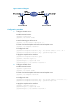
TCP RTC many-to-one relay configuration example
Network requirements
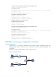
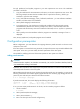
As shown in Figure 10, Router A and Router C serving as TCP_11_Clients are connected to terminal
devices. Router B serves as the relay server TCP_N1_Server.
• The listening port of the relay server is 2000.
• Each TCP_11_Client is connected to a terminal through the asynchronous serial interface Async
1/0.
• The two TCP_11_Clients have the same terminal number of 1.
Figure 10 Network diagram
Router A
1.1.1.1
Router B
1.1.1.3
Router C
1.1.1.2
Service
terminal
Service
terminal
Async1/0 Async1/0