
R2511-HP MSR Router Series Terminal Access Configuration Guide(V5)


50
# Create a terminal template and enter terminal template view.
[Sysname] rta template rtcclient
# Configure the VTY.
[Sysname-rta-template-rtcclient] vty 0 rtc-client remote 1.1.1.3 3000 udp local-port
3001 source 1.1.1.1
[Sysname-rta-template-rtcserver] quit
# Apply the template to the interface.
[Sysname] interface Serial2/0
[Sysname-Serial2/0] link-protocol hdlc
[Sysname-Serial2/0] rta terminal rtcclient 1
2. Configure the UDP_11_Server (Router B):
# Enable terminal access relay.
<Sysname> system-view
[Sysname] rta relay enable
# Create a terminal template and enter terminal template view.
[Sysname] rta template rtcserver
# Configure the VTY.
[Sysname-rta-template-rtcserver] vty 0 rtc-server remote 1.1.1.1 remote-port 3001 udp
local-port 3000 source 1.1.1.3
[Sysname-rta-template-rtcserver] quit
# Apply the template to the interface.
[Sysname] interface Serial2/0
[Sysname-Serial2/0] link-protocol hdlc
[Sysname-Serial2/0] rta terminal rtcserver 1
UDP RTC one-to-many configuration example
Network requirements
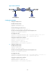
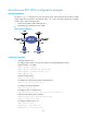
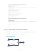
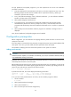
As shown in Figure 12, Router A and Router C serve as UDP_11_Clients, and Router B serves as a
UDP_1N_Server. Router A and Router C are connected to a terminal device through Serial 2/0
respectively.
The server uses UDP port 3000 and the clients use UDP port 3001.
Figure 12 Network diagram
Synchronous
terminal B
Synchronous
terminal A
Router A
Router C
Router B
Serial2/0
1.1.1.1
Serial2/0
1.1.1.2
Serial2/0
1.1.1.3