
R2511-HP MSR Router Series Terminal Access Configuration Guide(V5)


3
The monitoring terminal at the data center and the monitored terminal are each connected to a different
router through a serial interface, and the routers exchange data with each other through an IP network.
Normally, the router connected to the monitoring device acts as the terminal access initiator (the RTC
client). The monitoring device is always ready to initiate a connection request at any time to access the
data on the monitored device. The router connected to the monitored terminal acts as the terminal access
receiver (the RTC server) and is always ready to receive the connection requests from the monitoring
device and send monitored data in response. RTC terminal access also supports TCP-based many-to-one
transparent data transmission and UDP-based one-to-many transparent data transmission.
RTC terminal access serves the following purposes:
• Enabling the monitoring device to manage and monitor remote terminals.
• Sharing data among multiple terminals such as radar devices.
• Collecting data from remote terminals.
• Fulfilling the functions of a multiplexing device and transmitting data over IP networks for easy
network upgrade.
Typical applications of terminal access
Terminal access is widely used in networks where large numbers of FEPs are deployed, such as banking,
postal service, taxation, customs, and civil aviation. This document uses a banking system as an example
to describe terminal access functions, configuration, and applications. Figure 1 sh
ows a typical terminal
access application.
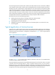
Figure 1 Typical terminal access application
As shown in Figure 1, the arrowhead of the dotted line indicates the direction of an established TCP
connection, from the initiator to the receiver.
The purple dotted line represents TTY/Telnet/ETelnet/SSH terminal access. The bank outlet is connected
to the FEP of the branch through Router A, which is capable of terminal access, over an IP network.
Banking services run on the FEP, and the information entered by an employee at the bank outlet is sent
to the FEP through Router A. The FEP then sends the corresponding service display to the service terminal
though Router A, thereby implementing data exchange between the outlet and the branch.