
R2511-HP MSR Router Series Terminal Access Configuration Guide(V5)

77
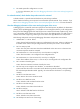
Serial
interfac
e
DB-25 DB-9
RJ-45 (for
telecom/banks)
Signal
Signal
direction
Signal description
Asynchro
nous
serial
interface
5 8 8 / 7 CTS
Æ
Clear to send
6 6 7 / 3 DSR
Æ
Data set ready
3 2 6 / 5 RxD
Æ
Receive data
7 5 5 / 4 GND - Logical ground
8 1 4 / 1 DCD
Æ
Data carrier detect
2 3 3 / 6 TxD
Å
Transmit data
20 4 2 / 2 DTR
Å
Data terminal ready
4 7 1 / 8 RTS
Å
Request to send
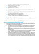
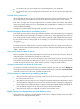
Terminal access converters are exclusively used for 8AS cables (RJ-45 for banks) and 16AS cables
(RJ-45 for banks) to connect to terminals. One end of the cable is an RJ-45 receptacle for
connecting to a standard network cable, and the other end is a DB-25 receptacle for connecting
to a terminal. The following table describes the pins of the terminal access converter.
RJ-45 (female) DB-25 (female) Si
g
nal
1 8 DCD
2 6 DSR
3 20 DTR
4 7 GND
5 2 TxD
6 3 RxD
7 4 RTS
8 5 CTS
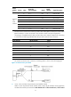
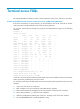
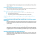
The common terminal access connection in banking systems is shown in the following figure:
Figure 13 Terminal access joint detail
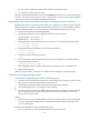
2. 3-wire, 5-wire, and 8-wire asynchronous serial interface cables
When a 3-wire asynchronous serial interface cable is used, dsr/dtr and flow control signal lines
are absent. This means you must use the undo detect dsr-dtr and flow-control none (or flow-control