
R2511-HP MSR Router Series Voice Configuration Guide(V5)

91
E1 R2 signaling and digital E&M signaling configuration
example
Network requirements
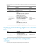
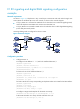
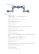
As shown in Figure 23, Telephones in City A and City B communicate with each other through voice
routers (Router A and Router B) across an IP network, as shown in the network diagram.
• In City A, Router A is connected to a PBX with an E1 subscriber line on which R2 signaling travels,
and to the telephone at 0101003 with an FXS voice subscriber line.
• In City B, Router B is connected to a PBX with an E1 subscriber line on which digital E&M signaling
(in the delay start mode) travels.
One-stage dialing mode is configured on the two routers.
Figure 23 Network diagram
Configuration procedure
1. Configure Router A:
# Configure the IP address 1.1.1.1/24 for the interface Ethernet 2/1.
<RouterA> system-view
[RouterA] interface ethernet 2/1
[RouterA-Ethernet2/1] ip address 1.1.1.1 255.255.255.0
[RouterA-Ethernet2/1] quit
# Create a TS set on the interface Ethernet 1/1.
<RouterA> system-view
[RouterA] controller e1 1/1
[RouterA-E1 1/1] timeslot-set 1 timeslot-list 1-31 signal r2
[RouterA-E1 1/1] quit
# Create a POTS voice entity corresponding to telephone number 010-1003 for the FXS interface.
[RouterA] system-view
[RouterA] voice-setup
[RouterA-voice] dial-program
[RouterA-voice-dial] entity 1003 pots
# Configure a target match-template for the POTS voice entity.
[RouterA-voice-dial-entity1003] match-template 0101003
# Associate the POTS voice entity with FXS subscriber line 3/0.
[RouterA-voice-dial-entity1003] line 3/0