
R2511-HP MSR Router Series Voice Configuration Guide(V5)

163
[RouterA-voice-dial-entity2222] quit
[Router1-voice-dial] entity 1111 pots
[RouterA-voice-dial-entity1111] line 1/0
[RouterA-voice-dial-entity1111] match-template 1111
2. Configure Router B:
# Configure the Ethernet interface.
<RouterB> system-view
[RouterB] interface ethernet 2/1
[RouterB-Ethernet2/1] ip address 192.168.2.2 255.255.255.0
# Configure voice entities.
<RouterB> system-view
[RouterB] voice-setup
[RouterB-voice] dial-program
[RouterB-voice-dial] entity 2222 pots
[RouterB-voice-dial-entity2222] line 1/0
[RouterB-voice-dial-entity2222] match-template 2222
[RouterB-voice-dial-entity2222] quit
[RouterB-voice-dial]entity 1111 voip
[RouterB-voice-dial-entity1111] address sip ip 192.168.2.1
[RouterB-voice-dial-entity1111] match-template 1111
Configuration verification
With the above configuration, you can use telephone 1111 to call telephone 2222, or use telephone 2222
to call telephone 1111.
• On Router A, the global authentication method is adopted. All numbers use the same
authentication username routerA and the same password 1234 .
• On Router B, the authentication username and password of number 2222 are routerB and 1234
respectively.
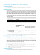
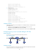
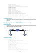
Configuring proxy server involved calling for SIP UAs
Network requirements
Two routers work as SIP UAs and SIP calls are made through a SIP server.
Figure 43 Network diagram
Configuration procedure
Routing-related configurations are beyond the scope of this example. This example assumes that Router
A, Router B, and the SIP server are reachable to each other.