
R2511-HP MSR Router Series Voice Configuration Guide(V5)

192
[RouterB-voice-dial-entity5000] match-template 5000
[RouterB-voice-dial-entity5000] line 2/0
[RouterB-voice-dial-entity5000] user 5000 password simple 5000
[RouterB-voice-dial-entity5000] quit
[RouterB-voice-dial] entity 5555 pots
[RouterB-voice-dial-entity5555] match-template 5555
[RouterB-voice-dial-entity5555] line 2/1
[RouterB-voice-dial-entity5555] user 5555 password simple 5555
[RouterB-voice-dial-entity5555] quit
[RouterB-voice-dial] entity 1000 voip
[RouterB-voice-dial-entity1000] address sip proxy
[RouterB-voice-dial-entity1000] match-template 1...
[RouterB-voice-dial-entity1000] quit
[RouterB-voice-dial] quit
# Enable SIP registration.
[RouterB-voice] sip
[RouterB-voice-sip] registrar ipv4 2.1.1.2
[RouterB-voice-sip] register-enable on
4. Verify the configurations:
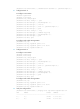
[RouterC-voice-server] display voice sip-server register-user all
user number status address
----------------------------------------------------------------------1000
1000 online 1.1.1.1:5060
1111 1111 online 1.1.1.1:5060
5000 5000 online 2.1.1.1:5060
5555 5555 online 2.1.1.1:5060
The four directory numbers are already registered, they cannot originate external calls, and Phone
5000 cannot originate calls to Phone 1000.
Configuring an area prefix
Network requirements
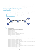
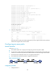
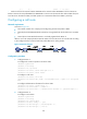
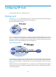
As shown in Figure 56:
• The internal numbers of a company are four-digit long and the area prefix is 8899.
• An external user needs to dial the area prefix 8899 before an internal number. The local SIP server
on Router C removes the area prefix from the dialed number and calls the four-digit internal number.
• The external phone attached to Router A is not registered with Router C.
• The internal phone attached to Router B is registered with Router C.
Figure 56 Network diagram
Configuration procedure
1. Configure Router C: