
R2511-HP MSR Router Series Voice Configuration Guide(V5)


269
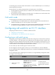
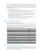
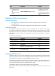
Figure 86 Network diagram
Configuration procedure
1. Configure device Voice A:
# Configure an IP address for each interface. (Details not shown.)
# Configure call watch group 1 to monitor local interfaces Ethernet 1/1 and Ethernet 1/2.
<VoiceA> system-view
[VoiceA] call-watch rule 1 local interface ethernet 1/1
[VoiceA] call-watch rule 1 local interface ethernet 1/2
# Associate E1 1/0 with call watch group 1 in hard mode.
[VoiceA] controller e1 1/0
[VoiceA-E1 1/0] call-watch group 1 hard
2. Configure Router A, Router B and device Voice B: configure an IP address for each interface.
(Details not shown.)
Monitoring remote IP addresses
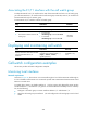
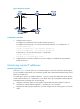
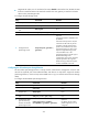
Network requirements
As shown in Figure 87, device Voice A is connected through two local links to Router B and through an
E1 link to the PBX to which Router A is connected to provide VoIP communication between Router A and
Router B in normal cases.
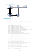
To enable device Voice A to disable interface E1 1/0 from routing calls destined for Router B when
remote interfaces Ethernet 1/1 and Ethernet 1/2 on Router B are not IP reachable so that the PBX can
immediately switch to a backup link, do the following:
• Configure a call watch group to work together with the NQA and Track module to monitor IP
connectivity to remote interfaces Ethernet 1/1 and Ethernet 1/2 on Router B.
• Apply the call watch group to interface E1 1/0 and configure the call watch group to work in soft
mode.