
R2511-HP MSR Router Series Voice Configuration Guide(V5)


306
[RouterB-voice-ivr] node 10 service
[RouterB-voice-ivr-node10] operation 2 media-play 10004 1
[RouterB-voice-ivr-node10] operation 3 end-call
[RouterB-voice-ivr-node10] select-rule operation-order 2 3 1
3. Verify configurations:
After dialing the number 300 at Telephone A, the subscriber hears the voice prompts of the audio
file bye.wav. After that, the call will be terminated.
Configuration example for three types of nodes
Network requirements
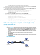
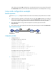
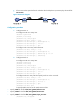
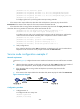
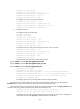
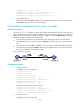
As shown in Figure 98, configure the IVR access number and customize Call node, Jump node and
Service node functions on Router B. After Telephone A originates a call through a SIP server by dialing
300 (the IVR access number of Router B), Router B plays the audio file welcome.wav. After that,
Telephone A jumps according to the voice prompts.
• If the subscriber presses the * key at Telephone A, the call jumps to the Service node and the
subscriber hears voice prompts of the audio file bye.wav. After that, the Service node releases the
call.
• If the subscriber presses the # key at Telephone A, the call jumps to the Call node and the subscriber
hears the voice of the audio file call.wav. After that, if the subscriber dials 1, the Call node executes
the call to number 500, and Telephone B rings.
Figure 98 Network diagram
Configuration procedure
1. Configure Router A:
# Configure POTS voice entity 100.
<RouterA> system-view
[RouterA] voice-setup
[RouterA-voice] dial-program
[RouterA-voice-dial] entity 100 pots
[RouterA-voice-dial-entity100] match-template 100
[RouterA-voice-dial-entity100] line 1/0
[RouterA-voice-dial-entity100] quit
# Configure VoIP voice entity 300 to Router B.
[RouterA-voice-dial] entity 300 voip
[RouterA-voice-dial-entity300] match-template 300
[RouterA-voice-dial-entity300] address sip ip 1.1.1.2
[RouterA-voice-dial-entity300] outband sip
2. Configure Router B:
# Configure POTS voice entity 500.