
R2511-HP MSR Router Series Voice Configuration Guide(V5)

318
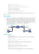
• Configure POTS entities.
• Configure VoFR entities.
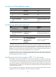
Configuring a call mode
Ste
p
Command Remarks
1. Enter system view.
system-view N/A
2. Enter voice view.
voice-setup N/A
3. Enter voice dial program
view.
dial-program N/A
4. Enter VoFR entity view.
entity entity-number vofr N/A
5. Configure a call mode.
call-mode dynamic
By default, the dynamic mode is
adopted.
6. Configure a channel to the
peer voice gateway.
address vofr-dynamic serial
interface-number dlci-number
By default, no channel to the peer
voice gateway is configured.
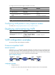
Configuring a call control protocol
Ste
p
Command Remarks
1. Enter system view.
system-view N/A
2. Enter serial interface view.
interface serial interface-number N/A
3. Specify the link layer protocol
for interface encapsulation as
frame relay.
link-protocol fr [ ietf |
nonstandard ]
By default, the link layer protocol
for interface encapsulation is PPP.
4. Enter interface DLCI view.
fr dlci dlci-number
N/A
5. Specify the VoFR call control
protocol on DLCI as
Huawei-compatible.
vofr huawei-compatible [ dce |
dte ]
By default, no VoFR call control
protocol is supported.
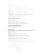
Configuring a CID selection mode
If multiple voice channels share a DLCI, a call collision will occur when the same FRF.11 sub-channel is
selected for calls respectively originated from the two sides. Different CID selection modes at the two
sides of the DLCI can reduce the possibility of call collisions.
To configure the CID selection mode:
Ste
p
Command Remarks
1. Enter system view.
system-view N/A
2. Enter serial interface view.
interface serial interface-number N/A
3. Enter interface DLCI view.
fr dlci dlci-number N/A
4. Configure the VoFR CID
selection mode.
cid selected-mode { max-poll |
min-poll }
Optional.
By default, CIDs are cyclically
selected in descending order.