
R2511-HP MSR Router Series Voice Configuration Guide(V5)

325
[RouterA-voice] dial-program
[RouterA-voice-dial] entity 0755 vofr
[RouterA-voice-dial-entity755] match-template 07552001
[RouterA-voice-dial-entity755] address vofr-dynamic serial 2/0 100
[RouterA-voice-dial-entity755] quit
# Configure the POTS entity (0101001).
[RouterA-voice-dial-entity755] entity 1001 pots
[RouterA-voice-dial-entity1001] match-template 0101001
[RouterA-voice-dial-entity1001] line 3/0
2. Configure Router B according to the network requirements and network diagram in Figure 102.
FRF.11 trunk
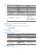
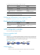
Network requirements
As shown in Figure 103, Telephone A (010-1001) attached to voice Router A in City A communicates with
Telephone B (0755-2001), which is attached to voice Router B in City B over a frame relay network.
Telephone A (010-1001) in City A is attached to the FXS subscriber line of Router A and can communicate
with Telephone B (0755-2001) in City B through an FRF.11 trunk by dialing 9. The PBX in City B is
connected to Router B through the FXO subscriber line. Telephone B (0755-2001) in City B can
communicate with Telephone A in City A through an FRF.11 trunk by dialing 8.
Figure 103 Network diagram
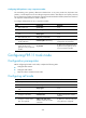
Configuration procedure
1. Configure Router A:
# Create a new frame relay class VoFR and set the maximum amount of voice bandwidth.
<RouterA> system-view
[RouterA] fr class vofr
[RouterA-fr-class-vofr] voice bandwidth 32000 reserved
[RouterA-fr-class-vofr] quit
# Enter Serial 2/0 view and configure the encapsulation format and interface type.
[RouterA] interface serial 2/0
[RouterA-Serial2/0] link-protocol fr ietf
[RouterA-Serial2/0] fr interface-type dce
# Enter DLCI 100 view and set the frame relay class to VoFR for DLCI.
[RouterA-Serial2/0] fr dlci 100
[RouterA-fr-dlci-Serial2/0-100] fr-class vofr
# Specify the call control protocol to be used by DLCI 100 as Huawei-compatible (DCE).