
R2511-HP MSR Router Series Voice Configuration Guide(V5)

32
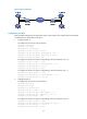
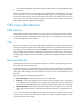
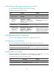
Figure 8 Network diagram
Perform an automatic busy tone detection test as follows:
1. Dial number 1002 from Telephone A (010-1001). The FXO interface on Router A plays a dial tone
to PBX A, which then transmits the tone to Telephone A. Then dial number 07552001 from
Telephone A. Telephone B rings. After Telephone B is picked up, the call is connected.
2. If you hang up Telephone A, PBX B plays a busy tone to Router A.
3. Use the vi-card busy-tone-detect command in voice view to start the detection. To ensure the
detection of the busy tone signal sent by PBX B, HP recommends that you run the command 2
seconds after on-hook.
4. (The console terminal displays "Begin to autodetect busy-tone, it will take about 12 seconds,
please wait...", which indicates that the busy tone detection is in progress. After the detection, the
terminal displays "Auto-detect busy-tone succeeded!", which indicates that the detection
succeeded.) Use the save command to save the detected busy tone parameters.
5. Repeat step 2 to verify whether the automatic busy tone detection succeeded. If so, Telephone A
will automatically be disconnected after PBX B plays busy tones to Router A for 4 seconds.
E&M subscriber line
E&M interface
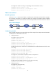
An ear & mouth or receive & transmit (E&M) interface uses a RJ-48 telephone cable to connect a PBX. The
PBX sends signals on the M (mouth) line and receives signals on the E (ear) line. The voice router receives
M signals from the PBX and sends E signals to the PBX. An E&M interface can only be connected to
another E&M interface.
When E&M is applied in VoIP communication, two or four voice wires can be used. There are two or four
signaling wires as well. Therefore, 4-wire analog E&M actually has six wires. In two-wire mode, voice is
transmitted over each wire in each direction simultaneously. In four wire mode, voice is transmitted over
each wire pair in each direction simultaneously.
E&M start mode
An E&M interface supports E&M signaling and divides each voice connection into trunk circuit side and
signaling unit side (similar to DCE and DTE).
An E&M interface provides on-hook/off-hook signals with minimum interference. Instead of using dial
tones, E&M interfaces use one of the following main start dial supervision signaling protocols:
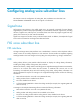
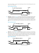
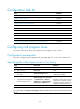
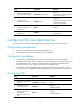
• Immediate start—As shown in Figure 9, the c
alling side goes off-hook, waits for a certain period of
time, and sends the dialed digits regardless of whether the called side is ready or not. If the called