
R2511-HP MSR Router Series Voice Configuration Guide(V5)

47
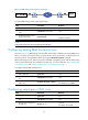
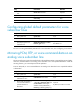
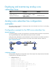
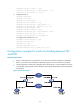
Figure 12 E&M analog control signals pass-through
To enable E&M analog control signals pass-through:
Step Command Remarks
1. Enter system view.
system-view N/A
2. Enter voice subscriber line
view.
subscriber-line line-number N/A
3. Enable E&M analog control
signals pass-through.
em-passthrough
Optional.
Disabled by default.
NOTE:
Configure this feature on the voice gateways of both sides.
Configuring analog E&M line failure tone
As shown in Figure 12, E&M analog control signals pass-through is enabled for the analog E&M line on
Router A. To notify an IP network failure or a peer failure to the Tone Generator, configure Router A to
play busy tones for analog E&M line failure by using the em-failure busytone command.
Before performing this task, make sure that both the E&M non-signaling mode and the E&M analog
control signals pass-through are enabled for the E&M line. For more information, see "Enabling E&M
n
on-signaling mode" and "Enabling E&M analog control signals pass-through."
T
o configure analog E&M line failure tone:
Step Command Remarks
1. Enter system view.
system-view N/A
2. Enter voice subscriber line
view.
subscriber-line line-number N/A
3. Configure analog E&M line
failure tone.
em-failure { busytone | silence }
Optional.
The default setting is silence.
Configuring output gain of SLIC chip
Step Command Remarks
1. Enter system view.
system-view N/A
2. Enter voice subscriber line
view.
subscriber-line line-number N/A
3. Configure the output gain of
the SLIC chip.
slic-gain { 0 | 1 }
Optional.
The default is 0 (0.8 dB).