
R2511-HP MSR Router Series Voice Configuration Guide(V5)

63
Task Remarks
Configuring basic parameters for a T1 voice interface Optional.
Configuring the voice subscriber line for a TS set Required.
Binding logical voice subscriber line to POTS entity Required.
Configuring R2 signaling
Configuring basic R2 signaling parameters Optional.
Configuring R2 digital line signaling Optional.
Configuring R2 interregister signaling Optional.
Configuring PRI Required.
Configuring digital E&M signaling Optional.
Configuring digital LGS signaling Optional.
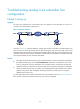
Configuring basic parameters for an E1 voice
interface
This section describes the basic parameters and procedures for configuring an E1 voice interface.
Configuring a TDM clock source
Introduction to TDM clock source
When digital voice E1 interfaces perform time-division multiplexing (TDM) timeslot interchange, it is
important for them to achieve clock synchronization to prevent frame slips and bit errors.
Depending on your configurations on E1 interfaces, the system adopts different clocking approaches.
When there is a voice co-processing module (VCPM) on the main board, the clock distribution principle
is as follows:
• If the clock mode is set to line for all interfaces, the clock on the interface with the lowest number is
adopted. If the interface goes down, the clock on the interface with the next lowest number is
adopted.
• If the clock mode is set to line primary for one interface, the clock on the interface is adopted. In one
system, you can do this on only one interface.
• If the line keyword is specified for one interface and the internal keyword for all others, the clock on
the interface is adopted.
• Generally, you cannot set the clock source for all interfaces in a system to internal. This is to prevent
frame slips and bit errors. You can do this, however, if the remote E1 interfaces adopt the line clock
source.
When there is no VCPM on the main board, the configuration of each MIM/FIC is independent, but the
clock mode of only one interface can be set to line primary on a device.
Suppose that you remove the FIC on an interface whose clock mode is set to line primary without
powering it off and that you set the clock mode to line primary for another interface. In this case, if you
re-insert the FIC, the clock mode of the FIC is restored to internal, instead of remaining line primary. In
this way, there is only one interface whose clock mode is set to line primary on a device. For example,
after the FIC in slot 5 (interface 5/0) whose clock mode is set to line primary is removed without being