
R2511-HP MSR Router Series Voice Configuration Guide(V5)

71
Binding logical voice subscriber line to POTS entity
Step Command Remarks
1. Enter system view.
system-view N/A
2. Enter E1/T1 interface view.
controller { e1 | t1 } slot-number N/A
3. Create a TS set according to
the selected signaling mode.
timeslot-set ts-set-number
timeslot-list timeslots-list signal
{ e&m-delay | e&m-immediate |
e&m-wink | fxo-ground |
fxo-loop | fxs-ground | fxs-loop |
r2 }
N/A
4. Exit E1/T1 interface view.
quit N/A
5. Enter voice view.
voice-setup N/A
6. Enter voice dial program view.
dial-program N/A
7. Create a POTS entity and
enter POTS entity view.
entity entity-number pots N/A
8. Bind a logical voice
subscriber line to a POTS
entity.
line slot-number:ts-set-number
Optional.
By default, no logical voice
subscriber line is bound to any
POTS entity.
Configuring R2 signaling
Introduction to R2 signaling
ITU-T recommendations Q.400 through Q.490 define the R2 signaling standards. However, the R2
signaling standards implemented in different countries and regions are ITU variants.
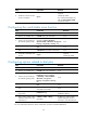
R2 signaling includes two categories: digital line signaling and interregister signaling. Digital line
signaling conveys status information about E1 trunks to describe whether the trunks are occupied,
released, or blocked. Interregister signaling transmits such information as address in multi-frequency
compelled approach. Generally, the calling side serves as the originating PBX and the called side serves
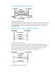
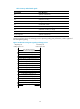
as the terminating PBX. Signals sent by the originating PBX are called forward signals and those sent by
the terminating PBX are called backward signals, as shown in Figure 18.
Figure 18 R2 signaling elem
ents
ITU-T digital line signaling
Digital line signaling is responsible for changing call statuses and conditions of a line. It functions to
identify and detect these four states: calling party goes off-hook and seizes the line, called party goes