
HP MSR2000/3000/4000 Router Series Interface Configuration Guide


35
Displaying and maintaining POS interfaces
Execute display commands in any view and reset commands in user view.
Task Command
Display information about one or
all POS interfaces.
display interface [ pos ] [ brief [ down ] ]
display interface [ pos [ interface-number ] ] [ brief [ description ] ]
Clear statistics of one or all POS
interfaces.
reset counters interface [ pos [ interface-number ] ]
Configuration example for directly connecting
routers through POS interfaces
Network requirements
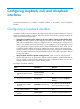
As shown in Figure 2, use a pair of single mode optic fibers (for receiving and sending data, respectively)
to connect the POS interfaces on Router A and Router B.
Encapsulate the interfaces with PPP.
Figure 2 Network diagram
Configuration procedure
1. Configure Router A:
# Configure interface POS 1/0, setting its physical parameters to defaults.
<RouterA> system-view
[RouterA] interface pos 1/0
[RouterA-Pos1/0] ip address 10.110.1.10 255.255.255.0
[RouterA-Pos1/0] link-protocol ppp
[RouterA-Pos1/0] mtu 1500
[RouterA-Pos1/0] shutdown
[RouterA-Pos1/0] undo shutdown
2. Configure Router B:
# Configure interface POS 1/0.
<RouterB> system-view
[RouterB] interface pos 1/0
# Set the clock mode to master and other physical parameters to defaults.
[RouterB-Pos1/0] clock master
[RouterB-Pos1/0] ip address 10.110.1.11 255.255.255.0
[RouterB-Pos1/0] link-protocol ppp
[RouterB-Pos1/0] mtu 1500