
HP MSR2000/3000/4000 Router Series Interface Module Guide

108
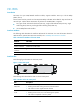
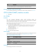
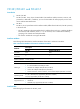
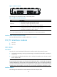
Figure 114 FIC-1CPOS panel
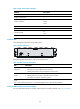
The following table describes the LEDs on the FIC-1CPOS panel.
Table 158 LEDs on the FIC-1CPOS panel
LED Descri
p
tion
LINK/ACT
• OFF means no link is present;
• ON means a link is present.
• Flashing means data is being received or transmitted.
LP/AL
• ON means a loopback interface is configured.
• Flashing means an alarm is present on the physical link.
Note:
AIS = Alarm indication signal; LFA = loss of frame alignment; RAI = Remote alarm indication
Fiber ports, optical fibers, and the connection method
For more information about fiber ports, optical fibers, and the connection methods, see "Fiber port."
Interface mode switchover
You can switch the FIC-1CPOS to operate in E1 and T1 interface modes at the command line interface
(CLI). Perform the following:
1. Insert the FIC-1CPOS into the FIC slot of the router and then power on the router.
2. Use the card-mode command in system view to set the interface mode. The following shows the
FIC-1CPOS module is inserted in slot 4 of the device.
# Enter system view
<Sysname> system-view
# Set the FIC-1CPOS to work in the E1 interface mode.
[Sysname] module-mode slot 4 e1
# Set the FIC-1CPOS to work in the T1 interface mode.
[Sysname] module-mode slot 4 t1
E1/T1 interface module
• FIC-2E1
• FIC-4E1
• FIC-4E1-F
• FIC-8E1
• FIC-4T1-F