
HP MSR2000/3000/4000 Router Series Interface Module Guide

140
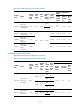
Product
code
Name
Center
wavele
ngth
(nm)
Fiber
mod
e
Optical
fiber
diame
ter
(μm)
Mod
el
band
widt
h
(MHz
*km)
Tran
smis
sion
dista
nce
Interface inde
x
(dBm)
Output
optical
power
Receive
sensitivit
y
Optic
al
satur
ation
MMF
62.5/1
25
500
550
m
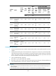
JD061A
HP X125 1G
SFP LC LH40
1310nm
Transceiver
1310 SMF 9/125 N/A
40
km
-2 to +5 ≤-22
≤-3
JD062A
HP X120 1G
SFP LC LH40
1550nm
Transceiver
1550 SMF 9/125 N/A
40
km
-4 to +1 ≤-21
≤-3
JD063B
HP X125 1G
SFP LC LH70
Transceiver
1550 SMF 9/125 N/A 70km
-4 to +2 ≤-22
≤-3
JD103A
HP X120 1G
SFP LC LH100
Transceiver
1550 SMF 9/125 N/A
100k
m
0 to +5 ≤-30 ≤-9
JD098B
HP X120 1G
SFP LC BX
10-U
Transceiver
1310(T
X)
1490(R
X)
SMF 9/125 N/A 10km
-9 to -3 ≤-18.7 ≤-3
JD099B
HP X120 1G
SFP LC BX
10-D
Transceiver
1490(T
X)1310(
RX)
SMF 9/125 N/A 10km
-9 to -3 ≤-18.7 ≤-3
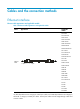
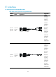
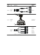
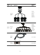
Connecting an optical fiber
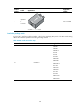
1. Insert the SFP/XFP transceiver module to the SFP/XFP interface on the interface module or service
module.
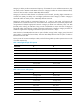
2. Identify the Rx and Tx ports on the SFP transceiver. Plug the LC connector at one end of one fiber
cable into the Rx port of the router and the LC connector at the other end into the Tx port of the peer
device. Plug the LC connector at one end of another fiber cable into the Tx port of the router and
the LC connector at the other end to the Rx port of the peer device.
3. View the LINK LED after connection.
• If the LED is on, the optical fiber link is present.
• If the LED is off, no link is present. This may be because the TX and Rx port of the optical fiber are
not connected correctly. In this case, connect the optical fiber again.
CAUTION:
•
Never stare into an open optical Ethernet interface, because invisible rays may be emitted from the optical
Ethernet interface.
• Cover the dust cover if no optical fiber connector is connected to the optical Ethernet interface.