
HP MSR2000/3000/4000 Router Series Interface Module Guide


46
Interface LEDs
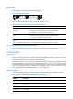
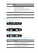
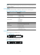
MIM-1ATM-OC3 panel is shown in the following figure:
Figure 42 MIM-1ATM-OC3 panel
The following table describes the LEDs on the MIM-1ATM-OC3 panel.
Table 65 Description for the LEDs on the MIM-1ATM-OC3 panel
LED Descri
p
tion
LINK/ACT
• ON means carrier signal has been received.
• Flashing means data is being received or/and transmitted.
• OFF means no carrier signal has been received.
LP/AL
• ON means the interface is in a loopback.
• Flashing means an AIS, LFA, or RAI alarm signal is present.
• OFF means no loopback or alarm is present.
Note:
LFA = Loss of frame alignment; AIS = Alarm indication signal; RAI = Remote alarm indication.
Fiber ports, optical fibers, and the connection method
For more information about fiber ports, optical fibers, and the connection methods, see "Fiber port."
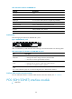
MIM-IMA-8E1
Introduction
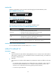
8-port E1 ATM inverse multiplexing interface module (MIM-IMA-8E1) provides four/eight E1 interfaces
that support the IMA (inverse multiplexing for ATM) technology.
The IMA technology combines multiple low-speed links into a group to support a high-speed ATM cell
stream: It distributes an ATM cell stream over multiple low-speed E1 links on cell by cell basis at the
transmission end and reassembles the cells on the low-speed E1 links into the original stream at the far
end. This technology provides a scalable and cost-effective solution, and is commonly used in
plesiochronous digital hierarchy (PDH) networks to transport ATM cells.
Interface attributes
The following table describes the interface attributes of the MIM-IMA-4E1/MIM-IMA-8E1 module:
Table 66 Interface attributes of the MIM-IMA-4E1/ MIM-IMA-8E1
Attribute Description
Connector DB68
Number of
connectors
1
Interface standard
ITU-G.703, ITU-G.704
Interface rate 2.048 Mbps