
HP MSR2000/3000/4000 Router Series MPLS Configuration Guide

161
224.0.0.0/24 Direct 0 0 0.0.0.0 NULL0
255.255.255.255/32 Direct 0 0 127.0.0.1 InLoop0
CEs of the same VPN can ping each other, whereas those of different VPNs cannot. For example, CE 1
can ping CE 3 (10.3.1.1), but it cannot ping CE 4 (10.4.1.1).
Configuring MPLS L3VPN over a GRE tunnel
Network requirements
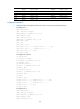
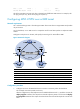
CE 1 and CE 2 belong to VPN 1. The PEs support MPLS. The P router does not support MPLS and provides
only IP functions.
On the backbone, use a GRE tunnel to encapsulate and forward VPN packets to implement MPLS
L3VPN.
Configure tunnel policies on the PEs, and specify the tunnel type for VPN traffic as GRE.
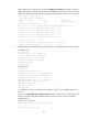
Figure 50 Network diagram
Device Interface IP address
Device
Interface
IP address
CE 1 Eth1/1 10.1.1.1/24 P POS5/0 172.1.1.2/24
PE 1 Loop0 1.1.1.9/32
POS5/1
172.2.1.1/24
Eth1/1 10.1.1.2/24
PE 2
Loop0
2.2.2.9/32
POS5/1 172.1.1.1/24 Eth1/1 10.2.1.2/24
Tunnel0 20.1.1.1/24
POS5/0
172.2.1.2/24
CE 2 Eth1/1 10.2.1.1/24
Tunnel0
20.1.1.2/24
Configuration procedure
1. Configure an IGP on the MPLS backbone to ensure IP connectivity within the backbone:
This example uses OSPF. (Details not shown.)
After the configurations, OSPF adjacencies are established between PE 1, P, and PE 2. Execute the
display ospf peer command. The output shows that the adjacency status is Full. Execute the display
ip routing-table command. The output shows that the PEs have learned the loopback route of each
other.