
HP MSR2000/3000/4000 Router Series MPLS Configuration Guide
164
Local AS number: 100
Total number of peers: 1 Peers in established state: 1
Peer AS MsgRcvd MsgSent OutQ PrefRcv Up/Down State
10.1.1.1 65410 4 4 0 2 00:00:13 Established
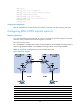
5. Configure an MP-IBGP peer relationship between PEs:
# Configure PE 1.
[PE1] bgp 100
[PE1-bgp] peer 2.2.2.9 as-number 100
[PE1-bgp] peer 2.2.2.9 connect-interface loopback 0
[PE1-bgp] address-family vpnv4
[PE1-bgp-vpnv4] peer 2.2.2.9 enable
[PE1-bgp-vpnv4] quit
[PE1-bgp] quit
# Configure PE 2 in the same way that PE 1 is configured. (Details not shown.)
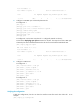
# Execute the display bgp peer vpnv4 command on the PEs. The output shows that a BGP peer
relationship has been established between the PEs and has reached the Established state.
[PE1] display bgp peer vpnv4
BGP local router ID: 1.1.1.9
Local AS number: 100
Total number of peers: 1 Peers in established state: 1
Peer AS MsgRcvd MsgSent OutQ PrefRcv Up/Down State
2.2.2.9 100 5 7 0 2 00:00:43 Established
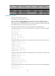
6. Configure a GRE tunnel:
# Configure PE 1.
[PE1] interface tunnel 0 mode gre
[PE1-Tunnel0] source loopback 0
[PE1-Tunnel0] destination 2.2.2.9
[PE1-Tunnel0] ip address 20.1.1.1 24
[PE1-Tunnel0] mpls enable
[PE1-Tunnel0] quit
# Configure PE 2.
[PE2] interface tunnel 0 mode gre
[PE2-Tunnel0] source loopback 0
[PE2-Tunnel0] destination 1.1.1.9
[PE2-Tunnel0] ip address 20.1.1.2 24
[PE2-Tunnel0] mpls enable
[PE2-Tunnel0] quit
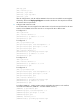
Verifying the configuration
# After the configurations, the CEs can learn the interface routes from each other. Take CE 1 as an
example:
[CE1] display ip routing-table