
HP MSR2000/3000/4000 Router Series Voice Configuration Guide


72
Examples
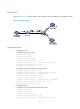
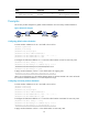
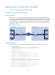
As shown in Figure 29, Router A and Router B connect to each other through an IP link and an E1 link.
The telephones at two sides call each other through the E1 link. This section provides examples for
configuring number sending modes to achieve different call policies.
Figure 29 Network diagram
Configuring basic settings
1. Configure Router A:
# Configure a timeslot set using R2 signaling for controller E1 1/1.
<RouterA> system-view
[RouterA] controller e1 1/1
[RouterA-E1 1/1] timeslot-set 0 timeslot-list 1-31 signal r2
[RouterA-E1 1/1] quit
[RouterA] voice-setup
[RouterA-voice] dial-program
# Configure a match template to match 010….$ for POTS entity 1001 and bind line 1/1:0 to the
entity.
[RouterA-voice-dial] entity 1001 pots
[RouterA-voice-dial-entity1001] match-template 010....$
[RouterA-voice-dial-entity1001] line 1/1:0
# Configure a local number 2000 for POTS entity 2000, and bind line3/0 to the entity.
[RouterA-voice-dial] entity 2000 pots
[RouterA-voice-dial-entity2000] match-template 2000
[RouterA-voice-dial-entity2000] line 3/0
2. Configure Router B:
# Configure a timeslot set using R2 signaling for controller E1 1/1.
<RouterB> system-view
[RouterB] controller e1 1/1
[RouterB-E1 1/1] timeslot-set 0 timeslot-list 1-31 signal r2
[RouterB-E1 1/1] quit
# Configure a local number 1001 for POTS entity 1002, and bind line 3/0 to the entity.
[RouterB] voice-setup
[RouterB-voice] dial-program
[RouterB] voice-setup
[RouterB-voice] dial-program
Router A
Router B
Eth2/1
1.1.1.1/24
Eth2/1
1.1.1.2/24
E1 1/1
2000
1001
0101001
Telephone A
Telephone B
Telephone C
Telephone D
01001
E1 1/1
FXS 3/0
FXS 3/0
FXS 3/1
FXS 3/2