
R0106-HP MSR Router Series High Availability Configuration Guide(V7)

9
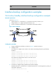
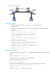
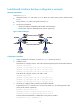
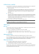
Figure 4 Network diagram
Configuration procedure
1. Assign IP addresses to interfaces, as shown in Figure 4. (Details not shown.)
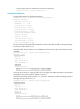
2. Configure routes:
# On Router A, configure static routes to 192.168.2.0/24 through the primary and backup
interfaces.
<RouterA> system-view
[RouterA] ip route-static 192.168.2.0 24 serial 2/1/0
[RouterA] ip route-static 192.168.2.0 24 serial 2/1/1
# On Router B, configure static routes to 192.168.1.0/24.
<RouterB> system-view
[RouterB] ip route-static 192.168.1.0 24 serial 2/1/0
[RouterB] ip route-static 192.168.1.0 24 serial 2/1/1
3. On Router A, configure track settings:
# Configure track entry 1 to monitor the link state of Serial 2/1/0.
[RouterA] track 1 Serial 2/1/0
# Associate track entry 1 with the backup interface Serial 2/1/1.
[RouterA] Serial 2/1/1
[RouterA-Serial 2/1/1] backup track 1
[RouterA-Serial 2/1/1] quit
Verifying the configuration
# Verify that the backup interface Serial 2/1/1 is in STANDBY state while the primary link is operating
correctly.
[RouterA] display interface-backup state
IB Track Information:
S2/1/1 Track: 1 State: STANDBY
# Shut down the primary interface Serial 2/1/0.
[RouterA] interface serial 2/1/0
[RouterA-Serial2/1/0] shutdown
# Verify that the backup interface Serial 2/1/1 comes up after the primary link goes down.
[RouterA-Serial2/1/0] display interface-backup state
IB Track Information:
S2/1/1 Track: 1 State: UP