
R0106-HP MSR Router Series High Availability Configuration Guide(V7)

10
Load-shared interface backup configuration example
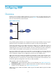
Network requirements
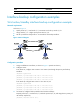
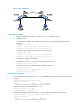
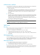
As shown in Figure 5:
• Configure Serial 2/1/1 and Serial 2/1/2 on Router A to back up the primary interface Serial
2/1/0.
• Assign Serial 2/1/1 higher priority than Serial 2/1/2.
• On the primary interface:
{ Specify the interface bandwidth used for traffic load calculation.
{ Set the upper and lower thresholds to 80 and 20, respectively.
Figure 5 Network diagram
Configuration procedure
1. Assign IP addresses to interfaces, as shown in Figure 5. (Details not shown.)
2. Configure routes:
# On Router A, configure routes to 192.168.2.0/24 through the primary and backup interfaces.
<RouterA> system-view
[RouterA] ip route-static 192.168.2.0 24 serial 2/1/0
[RouterA] ip route-static 192.168.2.0 24 serial 2/1/1
[RouterA] ip route-static 192.168.2.0 24 serial 2/1/2
# On Router B, configure routes to 192.168.1.0/24.
<RouterB> system-view
[RouterB] ip route-static 192.168.1.0 24 serial 2/1/0
[RouterB] ip route-static 192.168.1.0 24 serial 2/1/1
[RouterB] ip route-static 192.168.1.0 24 serial 2/1/2
3. On Router A, configure backup interfaces and traffic thresholds:
# Specify Serial 2/1/1 and Serial 2/1/2 to back up Serial 2/1/0, and assign them with a
priority of 30 and 20, respectively.
[RouterA] interface serial 2/1/0
[RouterA-Serial2/1/0] backup interface serial 2/1/1 30
[RouterA-Serial2/1/0] backup interface serial 2/1/2 20
# Set the expected bandwidth to 10000 kbps on the primary interface.
[RouterA-Serial 2/1/0] bandwidth 10000