
R0106-HP MSR Router Series Interface Command Reference(V7)

49
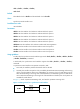
Table 7 describes the four clock selection options for a synchronous serial interface operating as a DTE.
The clock preceding the equal sign (=) is the DTE clock, and the clock that follows the equal sign is the
DCE clock.
Table 7 Clock options available for a synchronous serial interface operating as a DTE
Clock selection o
p
tion Descri
p
tion
DTEclk1 TxClk = TxClk, RxClk = RxClk.
DTEclk2 TxClk = TxClk, RxClk = TxClk.
DTEclk3 TxClk = RxClk, RxClk = TxClk.
DTEclk4 TxClk = RxClk, RxClk = RxClk.
DTEclk5 TxClk = Local, RxClk = Local.
Table 8 describes the clock selection options for a synchronous serial interface operating as a DCE. The
clock preceding the equal sign (=) is the DCE clock, and the clock that follows the equal sign is the clock
signal source.
Table 8 Clock options available for a synchronous serial interface operating as a DCE
Clock selection o
p
tion Descri
p
tion
DCEclk1 TxClk = Local, RxClk = Local.
DCEclk2 TxClk = Local, RxClk = Line.
DCEclk3 TxClk = Line, RxClk = Line.
Examples
# Configure Serial 2/1/0 operating as a DTE to use the clock selection option dteclk2.
<Sysname> system-view
[Sysname] interface serial 2/1/0
[Sysname-Serial2/1/0] clock dteclk2
code
Use code to set the digital signal coding format on a synchronous serial interface.
Use undo code to restore the default.
Syntax
code { nrz | nrzi }
undo code
Default
The digital signal coding format is NRZ.
Views
Synchronous serial interface view
Predefined user roles
network-admin