
R0106-HP MSR Router Series Layer 2 - LAN Switching Configuration Guide(V7)

45
• The regional root of MSTI 2 is Device C.
• The regional root of MSTI 0 (also known as the IST) is Device A.
Common root bridge
The common root bridge is the root bridge of the CIST.
In Figure 12, the co
mmon root bridge is a device in MST region 1.
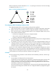
Port roles
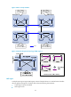
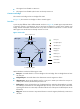
A port can play different roles in different MSTIs. As shown in Figure 14, an MST region comprises Device
A, Device B, Device C, and Device D. Port A1 and port A2 of Device A connect to the common root
bridge. Port B2 and Port B3 of Device B form a loop. Port C3 and Port C4 of Device C connect to other
MST regions. Port D3 of Device D directly connects to a host.
Figure 14 Port roles
MSTP calculation involves the following port roles:
• Root port—Forwards data for a non-root bridge to the root bridge. The root bridge does not have
any root port.
• Designated port—Forwards data to the downstream network segment or device.
• Alternate port—Serves as the backup port for a root port or master port. When the root port or
master port is blocked, the alternate port takes over.
• Backup port—Serves as the backup port of a designated port. When the designated port is invalid,
the backup port becomes the new designated port. A loop occurs when two ports of the same
spanning tree device are connected, so the device blocks one of the ports. The blocked port acts as
the backup.
• Edge port—Does not connect to any network device or network segment, but directly connects to a
user host.
Device A
(Root bridge)
Port A1 Port A2
Root port
Designated port
Normal link
Blocked link
Alternate port
Backup port
Master port
Boundary port
Device C
Device B Device D
Port A3 Port A4
Port B1
Port B2 Port B3
Port C1
Port C2
Port C3 Port C4
Port D1
Port D2
MST region
To the common root
To other MST regions
Edge port
Port D3