
R0106-HP MSR Router Series Layer 2 - LAN Switching Configuration Guide(V7)


95
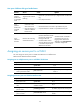
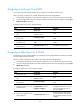
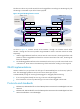
Figure 28 Network diagram
Configuration procedure
1. Configure Router A:
# Create VLAN 100, and assign GigabitEthernet 2/1/1 to VLAN 100.
<RouterA> system-view
[RouterA] vlan 100
[RouterA-vlan100] port gigabitethernet 2/1/1
[RouterA-vlan100] quit
# Create VLAN 200, and assign GigabitEthernet 2/1/2 to VLAN 200.
[RouterA] vlan 200
[RouterA-vlan200] port gigabitethernet 2/1/2
[RouterA-vlan200] quit
# Configure GigabitEthernet 2/1/3 as a trunk port to forward packets from VLANs 100 and 200
to Device B.
[RouterA] interface gigabitethernet 2/1/3
[RouterA-GigabitEthernet2/1/3] port link-type trunk
[RouterA-GigabitEthernet2/1/3] port trunk permit vlan 100 200
Please wait... Done.
2. Configure Device B in the same way Router A is configured. (Details not shown.)
3. Configure hosts:
a. Configure Host A and Host C to be on the same IP subnet. For example, 192.168.100.0/24.
b. Configure Host B and Host D to be on the same IP subnet. For example, 192.168.200.0/24.
Verifying the configuration
# Verify that Host A and Host C can ping each other, but they both fail to ping Host B. (Details not
shown.)
# Verify that Host B and Host D can ping each other, but they both fail to ping Host A. (Details not
shown.)
# Verify that VLANs 100 and 200 are correctly configured on Router A.
[RouterA-GigabitEthernet2/1/3] display vlan 100
VLAN ID: 100
VLAN type: Static
Route interface: Not configured
Description: VLAN 0100
Name: VLAN 0100
Tagged ports:
GigabitEthernet2/1/3